





Waveguide vs Coax: When a Waveguide Cable Assembly Is Worth the Cost
Choosing between a waveguide and a coaxial cable is one of the more consequential decisions in RF and microwave system design. For many engineers, coax is the default — it's flexible, widely available, and easy to work with. But above 18 GHz, or in high-power environments like radar and satellite ground stations, a waveguide cable assembly often delivers measurably better signal integrity, lower attenuation, and longer service life. This article walks through the technical and financial factors that determine when the higher upfront cost of a waveguide assembly is the right call.
Understanding Waveguide and Coaxial Cable Assemblies
What Is a Coaxial Cable Assembly?
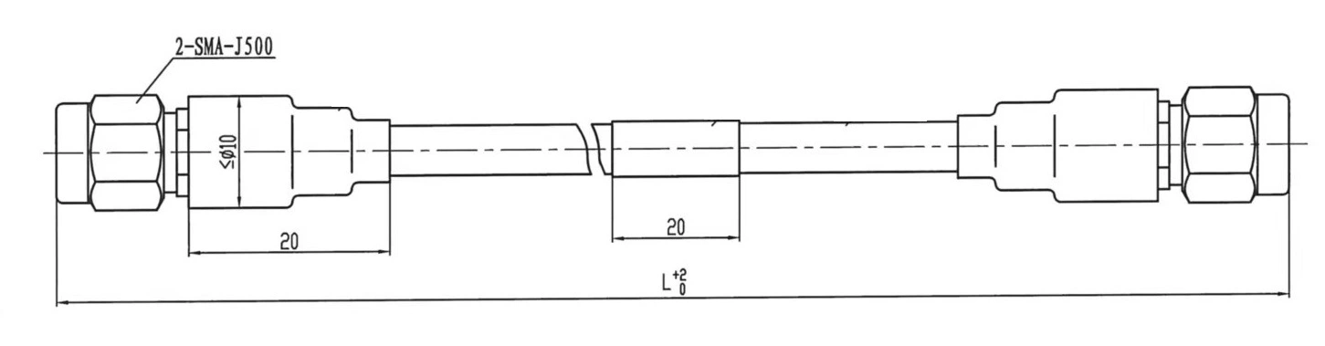
There is a center conductor, a dielectric barrier, a metallic shield, and an outer jacket that make up a coaxial cable system. Depending on the type of connection, it works well from DC to about 18–40 GHz and sends data in TEM (Transverse ElectroMagnetic) mode. Because it is small, flexible, and easy to end, coax is the most common way to connect lower-frequency radio frequencies in labs, on telecommunications equipment, and in everyday life.
What Is a Waveguide Cable Assembly?
A waveguide cable assembly is a hollow metal device that sends microwave signals in either TE (Transverse Electric) or TM (Transverse Magnetic) modes. Its cross-section is usually either rectangular or circular. Flexible types have a metal core that is twisted and interlocked with a protective jacket. This lets them bend and straighten themselves without breaking. Precision-machined flanges like CPR, UBR, or UG standards are usually part of these systems. They work in specific frequency ranges that depend on the size of the waveguide. For example, WR-90 covers the X-Band (8.2–12.4 GHz), and WR-28 covers the Ka-Band (26.5–40 GHz).
How Their Operating Frequency Ranges Compare
Coaxial wires work well over a wide frequency range, but as the frequency goes up, they lose more power in the insulator and conductor. Waveguide structures, on the other hand, have a clear cutoff frequency below which they won't send signals. Above that frequency, however, they lose signals much less than before. At 40 GHz, a flexible waveguide assembly can have insertion loss that is only a tenth of that of a similar coaxial cable. This is a big difference that has an immediate effect on system link costs and heat management.
Performance Comparison: When Waveguide Excels Over Coax
Lower Insertion Loss at High Frequencies
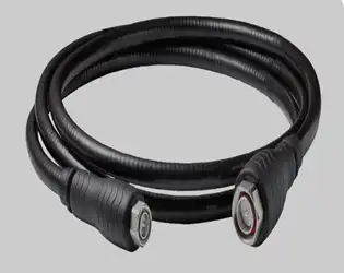
Due to skin effect losses in the center wire and dielectric heating, coaxial lines lose more signal as the frequency goes up. When it comes to millimeter-wave frequencies, a well-designed flexible waveguide cable assembly system can get insertion loss below 0.5 dB/m, while coaxial options in the same frequency range may go over 3–5 dB/m. This difference is not small for long-path links in SATCOM earth stations or airborne radar; it has a direct effect on the system noise figure and power efficiency.
Higher Power Handling Without Thermal Degradation
Waveguide structures can handle much higher CW and peak power levels without overheating because they don't have any dielectric material in the signal path (the hollow core is filled with air or vacuum). This is very important in high-power amplifier (HPA) output stages at satellite uplink facilities, where sending power at the kilowatt level is common. At these power levels, coaxial lines would need to be actively cooled or derated, which would make the system more complicated and cost more.
Durability and Phase Stability Under Mechanical Stress
One thing that sets premium flexible waveguide assemblies apart is that they keep their phase stability when they bend. When turning, high-end units keep the phase difference within ±2 to 5 degrees, which is important for readings with phased-array radar and vector network analyzers (VNAs). When mechanically cycled over and over, coaxial wires break down faster, even high-performance phase-stable types. Millions of flex cycles are built into flexible waveguide assemblies, which is a key condition for gimbaled antennas on marine and airborne platforms.
Cost Analysis and Procurement Considerations
Initial Cost vs. Total Cost of Ownership
A waveguide cable assembly usually costs a lot more up front than a similar coaxial solution. The difference can be very big depending on the frequency band, flange standard, and jacket material. But buying decisions that are only based on unit price often don't take into account the bigger picture. The total cost of ownership often supports the waveguide option in high-frequency, high-reliability uses. This is because it has lower system losses (lower amplifier drive needs), longer service intervals, and fewer field replacements.
Lead Times and Customization Requirements
Off-the-shelf coaxial cables have shorter lead times than custom waveguide assemblies. This is especially true for assemblies that need specific WR sizes, non-standard flange configurations, or special jacket materials for vacuum or outdoor environments. It should take between 4 and 8 weeks for procurement teams to plan for complex custom builds. Working with a company that has a lot of waveguides in stock and can make prototypes quickly can lower the risk of missing a deadline. At ADM, teams can get quick-turnaround samples and engineering support to make sure their ideas work before committing to large-scale production.
Supplier Reliability and Documentation Standards
If you want to use paperwork for defense, aerospace, or satellite uses, you have to. The people who work in procurement need VNA sweep data, VSWR plots, dimensional inspection records, and badges that show the goods can be tracked. Most coaxial systems from mass-market sellers don't have this much depth. As usual, a good waveguide cable assembly provider should give you full test data for each assembly, records of flange inspections, and compliance paperwork like ISO 9001 certification and RoHS conformance.
How to Decide: Is a Waveguide Cable Assembly Worth the Cost for Your Project?
Define Your Operating Frequency and Power Requirements First
Coax is generally the best choice if your machine works below 18 GHz with moderate power. When working at X-Band, Ku-Band, Ka-Band, or higher frequencies, or when your system sends a lot of power, it's easy to see why a waveguide assembly would be useful. First, figure out the frequency range and power budget. Then, check to see if the cable loss and power handling specs meet your link margin needs.
Evaluate Environmental and Installation Conditions
Flexible waveguide systems are better than solid waveguide plumbing when alignment flaws, differences in temperature expansion, or stress caused by vibrations can't be handled. When SATCOM terminals are used outside, the material of the jacket is important. Neoprene- and silicone-jacketed units that meet MIL-DTL-3922 standards protect against weather. Unjacketed or low-outgassing material versions are available for vacuum or lab settings. These installation-specific factors often play just as big a role in choosing a product as its electrical performance.
Balance Budget Against Long-Term Operational Risk
That being said, the cost of a broken RF link in a defense or satellite system is also real. When properly defined, waveguide systems lower the chance of failure while in use. The higher cost of a high-quality waveguide assembly is not an extra cost for projects where downtime could cost money or hurt the goal. Instead, it is an investment to lower risk.
Technical Support and Maintenance for Waveguide Cable Assemblies
Installation Best Practices
Check the fit of the flanges before putting them together. When you pair a covered flange with a grooved flange in the wrong way, for example, RF leakage and impedance discontinuities happen. Respect the minimum bend radius (MBR) of the assembly. Going beyond it forever changes the shape of the overlapping convolutions and causes VSWR spikes. For waveguide systems that are under pressure, use dry nitrogen to purge and check the integrity of the air seal before turning on the power.
Routine Inspection and Testing Protocols
The best way to find degradation early is to do regular VNA sweeps across the whole operating band. Check the faces of the flanges for dirt, corrosion, or mechanical damage that could make the RF interface less reliable. For outdoor applications, check the stability of the jacket once a year and after bad weather. GO/NO-GO gage checks on the position of the bolt holes make sure that the flange contact stays within the specifications over time.
Common Troubleshooting Scenarios
When VSWR spikes happen out of the blue, they are usually caused by a piece that was bent or kinked beyond the MBR, a dirty flange face, or a bolt that was torqued unevenly. When used for measurements, phase drift usually means that the core convolutions are wearing out mechanically. Moisture getting in through a broken jacket seal is the most common reason why insertion loss slowly rises over time in outdoor systems. Use dry air or nitrogen to put pressure on the joint to make sure the seal is still good.
Conclusion
The main things that determine whether to use coaxial or waveguide interconnects are frequency, power, and the environment in which the system will be used. Most of the time, coax works well below 18 GHz, but if your system needs to work at X-Band or higher, or if it needs to send a lot of power while keeping temperatures low, a flexible waveguide cable assembly will work much better over its lifetime. Even though it costs more up front, radar, SATCOM, and millimeter-wave test uses can't do without the technical cushion it gives.
FAQ
What frequency range makes a waveguide assembly necessary?
In general, waveguide designs are better at preventing signal loss than coaxial ones above 18 GHz. At Ka-Band (26.5–40 GHz) and higher, the difference in insertion loss is too big for link-budget-conscious designs to ignore.
How long does a custom waveguide assembly take to produce?
Lead times depend on how complicated the job is. WR-size kits with popular flange types usually ship in two to four weeks. It could take 6–8 weeks for complex setups that need non-standard jacket materials, special flange standards, or vacuum-compatible builds. Often, prototype runs can be sped up.
What is the difference between a flexible and a rigid waveguide?
A rigid waveguide has the lowest insertion loss, but it can't handle vibration or misalignment. A flexible waveguide assembly has a twisted metal core that lets it bend and spin while still working electrically well. This type of assembly is best used when mechanical adjustment is needed.
Can flexible waveguide assemblies be used outdoors?
Yes. Assemblies with MIL-DTL-3922-rated Neoprene or Silicone jackets are made to be used outside and can handle UV light, water, and changes in temperature. In harsh environments, the flange sealing and jacket continuity should be checked on a regular basis.
What test data should I request with a waveguide assembly order?
Ask for a full-band VNA sweep that shows VSWR and insertion loss, as well as a report on the planarity of the flange and a pressure/leak test result for systems that are under pressure. Manufacturers who are ISO 9001 approved should include these as common items.
Get a Custom Waveguide Cable Assembly Quote from ADM
Precision waveguide cable assembly and RF interconnects from ADM have been sold to defense, satellite, and industry users for more than 20 years. We have been making waveguide cable assemblies for a long time and can offer full-band VNA-tested assemblies, fast development, quality documentation that is ISO 9001-certified, and direct engineering support. We'll get you a solution that works if you tell us your frequency band, flange standard, and application. To get a price, email us at craig@admicrowave.com.
References
1. Pozar, D. M. Microwave Engineering, 4th ed. John Wiley & Sons, 2012.
2. IEEE Transactions on Microwave Theory and Techniques. "Loss Characteristics of Rectangular Waveguide at Millimeter-Wave Frequencies." IEEE, 2018.
3. MIL-DTL-3922 — Flexible Waveguide, Radio Frequency, General Specification for. U.S. Department of Defense, 2003 (revised).
4. Collin, R. E. Foundations for Microwave Engineering, 2nd ed. IEEE Press / Wiley-Interscience, 2001.
5. Bahl, I., and Trivedi, D. K. "A Designer's Guide to Microstrip Line." Microwaves Magazine, 1977.
6. IEC 62153-4-7 — Metallic Communication Cable Test Methods: RF Leakage of Coaxial Cables and Assemblies. International Electrotechnical Commission, 2015.
YOU MAY LIKE
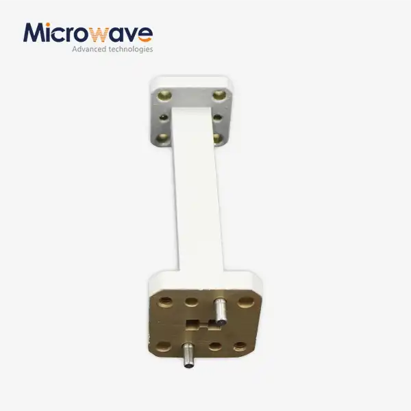 VIEW MOREWaveguide Straights and Transitions
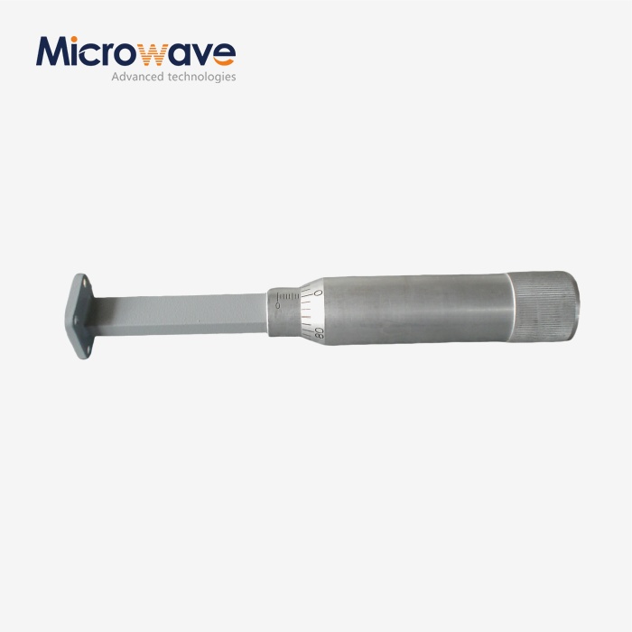 VIEW MOREWaveguide Sliding Termination
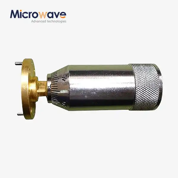 VIEW MOREWaveguide Sliding Short
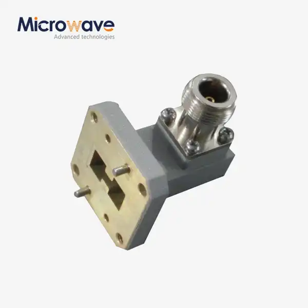 VIEW MOREDouble Ridged WG To Coaxial Adapter
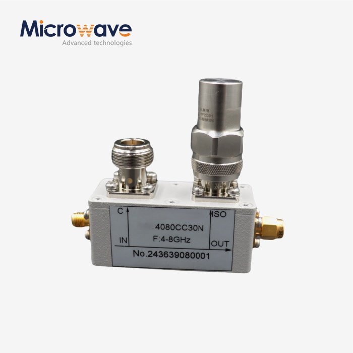 VIEW MORECoaxial Directional Coupler
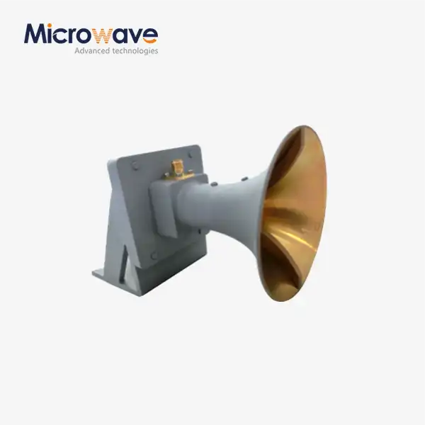 VIEW MOREUltra Double-ridged Horn Antenna
 VIEW MORELadder Membrane Square Dual Circular Polarization Horn Antenna
 VIEW MOREDual Linear Broadband Circular Polarization Horn Antenna
