




Why Do Deep Space Networks Rely on the Cassegrain Antenna?
When engineers at NASA's Deep Space Network (DSN) need to receive a signal from a spacecraft billions of kilometers away, every fraction of a decibel matters. The Cassegrain antenna has earned its place as the standard solution for these applications. Its dual-reflector architecture — a large primary parabolic dish paired with a secondary hyperbolic sub-reflector — folds the signal path back toward the dish vertex, placing sensitive low-noise amplifiers at the rear hub. This eliminates long waveguide runs, reduces insertion loss, and dramatically improves the Gain-to-Noise Temperature (G/T) ratio that deep space telemetry demands.
Understanding the Cassegrain Antenna and Its Working Principle
From Optical Telescope to RF Engineering
The Cassegrain idea comes from the 1600s, when Laurent Cassegrain used dual-mirror lenses in astronomy. Later, RF experts changed the shape to work with microwave bands. This makes an antenna whose effective focal length is much longer than its physical depth. This property makes the beam more focused and reduces spherical aberration.
How the Dual-Reflector System Works
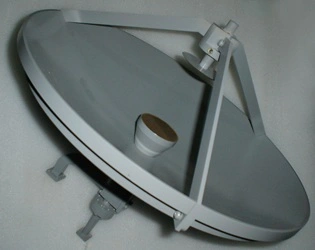
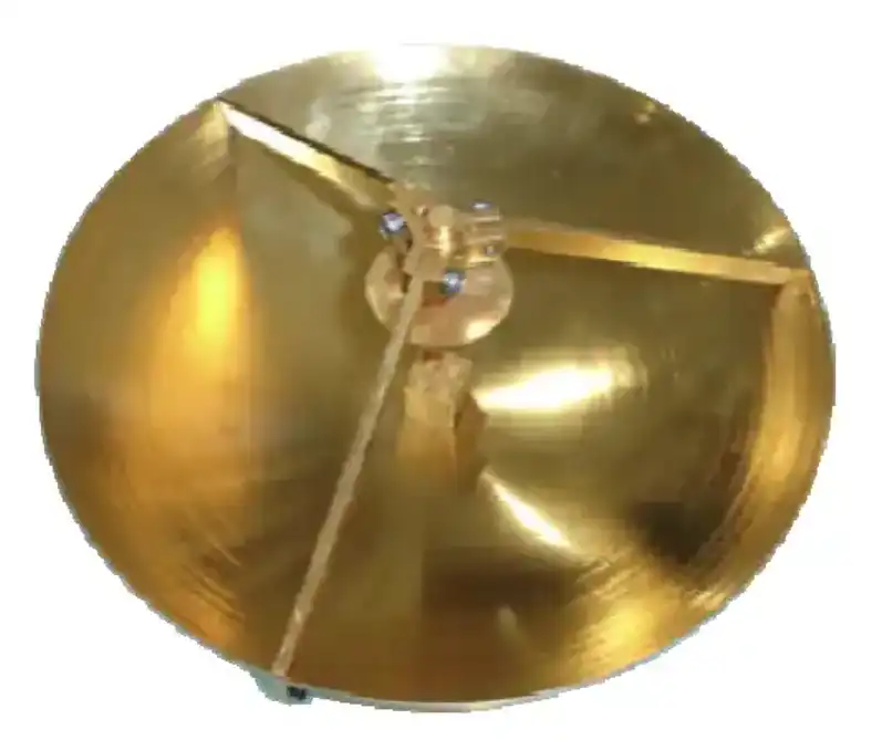
When a signal comes in, it hits the big main parabolic reflector, bounces off of it and onto the secondary hyperbolic sub-reflector. It then goes back through a small hole at the dish's vertex and into the feed horn. Behind the dish are heavy electronics like low-noise block converters and high-power amplifiers. Engineers no longer have to hang a center point in the air and run long waveguide wires to it.
Key Technical Specifications for Deep Space Use
Very good performance. For communication between planets, Cassegrain systems usually work in the S-band (2–4 GHz), X-band (8–12 GHz), and Ka-band (26.5–40 GHz) ranges. Cross-Polarization Discrimination (XPD) is more than 30 dB, surface RMS accuracy is often better than 0.2 mm for Ka-band compliance, and aperture efficiency is 60–70%. These numbers tell us exactly how much a secure link costs when a spaceship is close to Saturn's orbit.
Why Cassegrain Antennas Excel in Deep Space Networks
When you put different types of reflector antennas next to each other, the Cassegrain design always does better in the conditions of deep-space ground stations. Why is that? Here are the main performance benefits that show why:
- Lower noise temperature: The feed horn points toward the cool sky via the sub-reflector rather than toward the warm ground. This reduces thermal noise pickup and raises G/T — the single most important figure of merit for deep space reception.
- Compact structure with a long effective focal length: The folded optical path produces a shallow main reflector (f/D ratio of 0.6–0.8), which reduces wind load, lowers structural weight, and simplifies pedestal design without sacrificing gain.
- Rear-mounted electronics: Amplifiers and converters sit behind the main dish at the hub, where technicians can service them at ground level. Mean Time To Repair (MTTR) drops significantly compared to prime-focus designs, where hardware hangs at the top of a feed tower.
- Reduced feed-support blockage: Because the feed assembly moves to the rear, the struts that hold it in a prime-focus design disappear. Side-lobe levels decrease, and the main beam stays cleaner — critical when ITU-R S.580 side-lobe envelope compliance is a regulatory requirement.
These benefits are not just ideas. Shaped Cassegrain antenna geometry is used by all three of NASA's 70-meter DSN dishes in Goldstone, Madrid, and Canberra. The same design principles are used for ESA's ESTRACK network. A Cassegrain ground station picks up the signal that Voyager 1 sends at about 160 bits per second from more than 23 billion kilometers away.
Procurement Considerations for B2B Clients: Selecting the Right Cassegrain Antenna
It's not enough to just compare description sheets to find the right dual-reflector antenna for a ground station scheme. Teams in charge of buying things need to look at a number of technical and business factors together.
Performance Metrics That Drive the Specification
The most important electrical factors to check are the noise temperature, sidelobe pattern compliance with FCC 25.209 and ITU-R S.580, and gain at the working frequency. VSWR should be less than 1.3:1 for professional earth stations. RMS error must be used to describe surface accuracy; λ/20 is the acceptable limit for the highest frequency in the band plan.
Quality Assurance and Acceptance Testing
Tough QA is what separates a trustworthy source from a dangerous one. For accurate main-reflector surface measurements, ask for Laser Tracker or photogrammetry results. Factory Acceptance Tests (FAT) are done in a near-field or compact antenna test range to make sure that the data on gain and pattern are correct before the product is shipped. For use outside, structural coatings must pass the ASTM B117 Salt Spray test, and the structure must be able to withstand wind speeds of up to 200 km/h in a test. Suppliers who are certified to ISO 9001:2015 leave a written record of their quality management that buying teams can check.
Customization and OEM Readiness
Most projects for deep space and satellite ground stations use aperture sizes that aren't standard, feed networks that aren't standard, or mounting arrangements that aren't standard. A provider with real in-house R&D capabilities, such as equipment for measuring Cassegrain antenna patterns, can make changes to a design quickly. Find out how long it takes to make a prototype and if the provider can send full technical paperwork packages that can be used to put together bigger system parts. These should include interface control documents and material compliance records.
Installation, Maintenance, and Long-Term Performance Optimization
Site Preparation and Precision Alignment
A geodetic scan makes sure that the base is stable and level before it is put in place. The center of the feed phase must line up perfectly with the focal axis of both reflectors. At Ka-band, even a small mismatch causes beam squint and measured gain loss. Professional installations always align the laser tracker during the final assembly step.
Routine Maintenance to Prevent Downtime
Inspection of the sub-reflector mounting brackets, feed horn connectors, and waveguide flanges on a regular basis stops small amounts of wear and tear. After a storm, the reflective surface panels should be checked again. Pressurization or desiccant systems can help keep the VSWR low over time in connector and waveguide joints that are exposed to outdoor humidity.
Upgrading Feed Systems for Evolving Frequency Plans
Satellite companies often move data from Ku-band to Ka-band or add capacity to V-band. The Cassegrain design allows for multi-band feed clusters at the hub without changing the structure of the main dish. This makes it easy to increase frequency coverage as mission needs change. This saves investment costs over many years of use.
Conclusion
The Cassegrain antenna has a place in networks for deep space because it is both physically and practically useful. The folded optical path raises G/T by cooling the feed toward the sky. The electronics are placed on the back, which lowers the risk of waveguide loss and upkeep, and the shallow dish shape handles wind loads in open areas. If B2B procurement teams are looking for reflector antennas for radar systems, radio astronomy facilities, or satellite ground stations, knowing these design principles will help them have better talks with suppliers and write better specifications. It is very important to choose a provider that has confirmed surface accuracy data, documented FAT results, and real customization capabilities; the task rests on it.
FAQ
Why does the Cassegrain design outperform a prime-focus dish at Ka-band?
Waveguide loss per meter is a lot higher at Ka-band than it is at lower frequencies. From the dish's focal point to the electronics at ground level, a prime-focus antenna needs a long cable run. The Cassegrain puts the LNA right behind the dish hub, so there is no need for that wire run. This keeps the signal strong where it counts most.
Does the sub-reflector block a meaningful portion of the aperture?
The blocked area is only a small part of the total aperture for dish diameters greater than about 50 wavelengths, which includes any commercial earth station bigger than about 2.4 meters at Ku-band. The small obstruction is more than made up for by the efficiency gains from the optical design.
Can a prime-focus dish be retrofitted into a Cassegrain system?
Most of the time, no. Prime-focus dishes are made with a deep shape (f/D of 0.3 to 0.4). For Cassegrain optics to work, the main reflector needs to be shallower (f/D of 0.6–0.8) so that the sub-reflector can be placed properly. Retrofitting changes the basic shape of the reflector and isn't usually a good idea.
How is standing-wave interference between the feed and sub-reflector managed?
Professional designs have a vertex-matching plate or a sub-reflector surface with a geometric form that spreads out center reflections. So, standing-wave energy doesn't come back to the feed horn as a VSWR spike. This keeps the impedance fixed across the working band.
Partner with ADM for Precision Cassegrain Antenna Solutions
For more than twenty years, ADM has sold defense, satellite, and research customers high-precision microwave antennas and RF parts. As a Cassegrain antenna maker with a lot of experience, we offer designs that are ISO 9001:2015-certified, antenna measurements up to 110 GHz that can be done in-house, quick prototype turnaround, and full technical documents for OEM integration. To talk about your ground station needs, email our engineering team at craig@admicrowave.com.
References
1. Ruze, J. — Antenna Tolerance Theory: A Review, Proceedings of the IEEE, 1966.
2. Rahmat-Samii, Y. & Imbriale, W.A. — Shaped Reflector Antenna Analysis, IEEE Transactions on Antennas and Propagation, 1980.
3. Imbriale, W.A. — Large Antennas of the Deep Space Network, JPL Deep Space Communications and Navigation Series, 2003.
4. Stutzman, W.L. & Thiele, G.A. — Antenna Theory and Design, 3rd Edition, Wiley, 2012.
5. ITU-R Recommendation S.580 — Radiation Diagrams for Use as Design Objectives for Antennas of Earth Stations Operating with Geostationary Satellites, International Telecommunication Union, 2004.
6. Balanis, C.A. — Antenna Theory: Analysis and Design, 4th Edition, Wiley, 2016.