





Return Path vs Direct Read in Variable Waveguide Attenuator Calibration
When calibrating a variable waveguide attenuator, choosing between Return Path and Direct Read methods directly impacts measurement accuracy and operational reliability. Return Path calibration analyzes reflected signals to determine attenuation precision, demanding sophisticated vector network analyzers and controlled environments. Direct Read calibration measures forward signal transmission, offering faster setup and simpler instrumentation. Both approaches serve mission-critical applications differently, and understanding these distinctions helps procurement teams specify the right calibration protocol for radar systems, satellite ground stations, and aerospace test equipment where signal integrity cannot be compromised.
Understanding Variable Waveguide Attenuators and Calibration Fundamentals
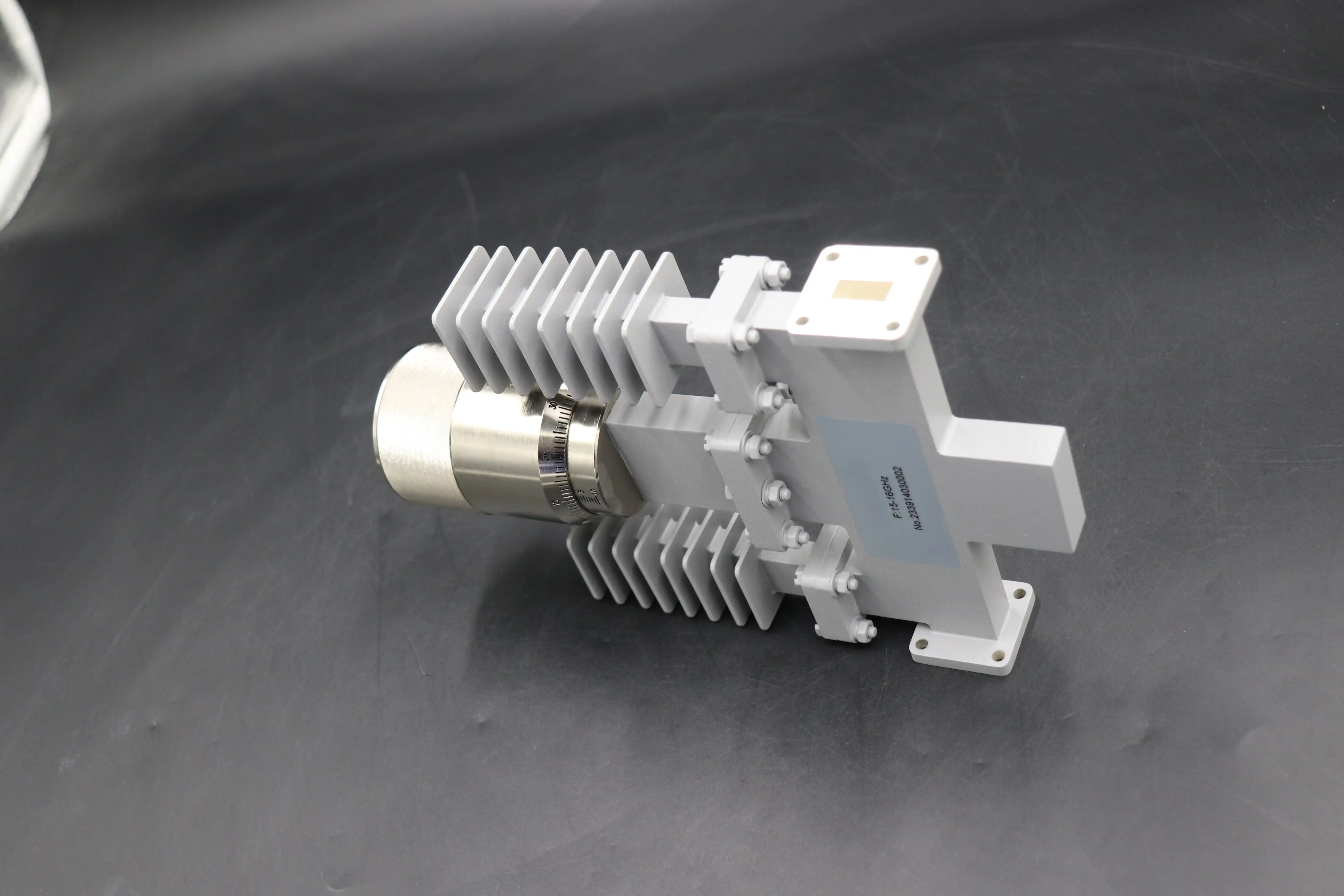
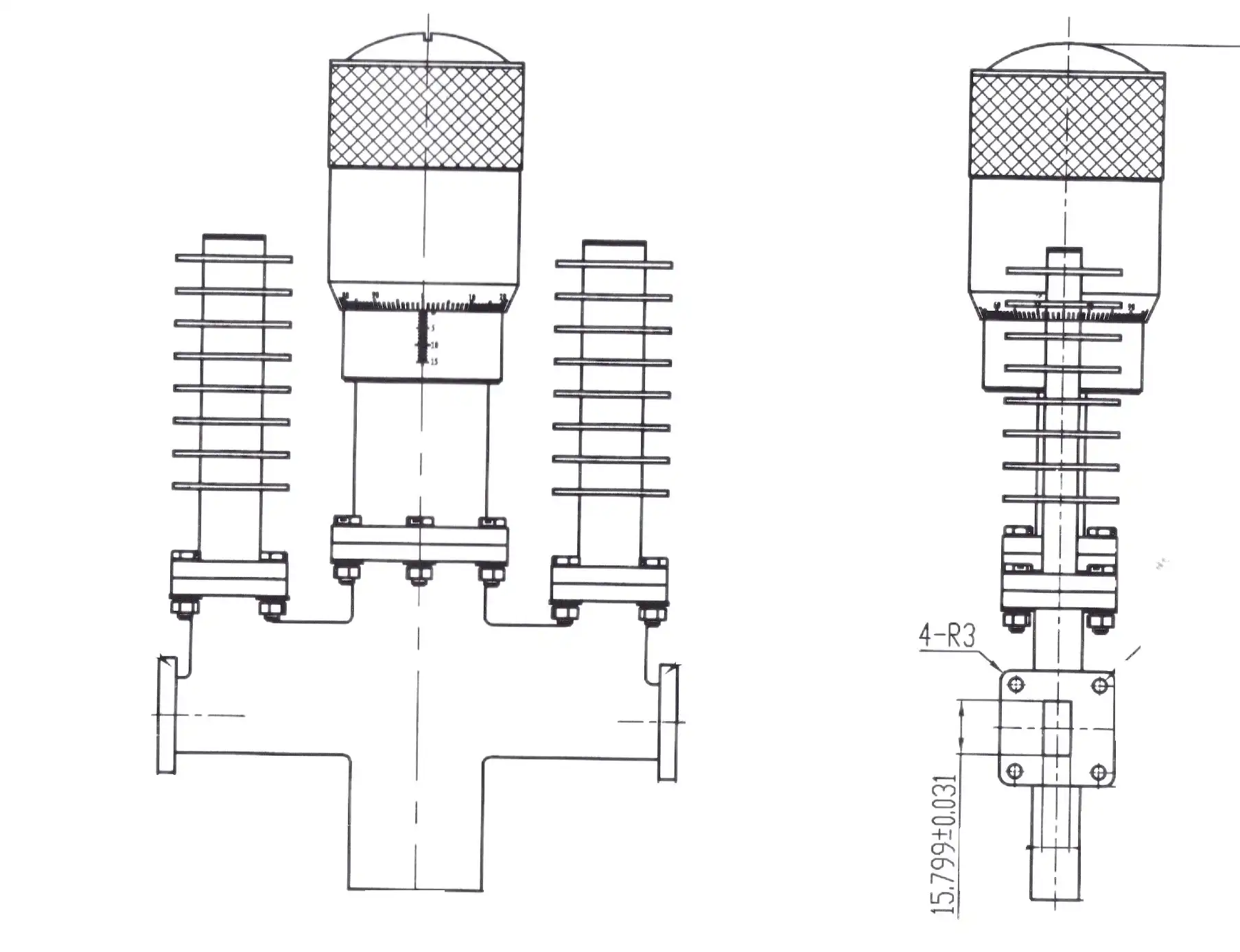
There is a high-precision microwave part called a variable waveguide attenuator that can change the signal amplitude within waveguide transmission lines without changing the frequency or phase too much. In contrast to fixed attenuators, these gadgets let you change the strength of the signal by using mechanical parts, usually a resistive vane that moves into the electric field or a rotary element that slowly absorbs electromagnetic energy. This ability to be adjusted solves important engineering problems, like keeping sensitive low-noise amplifiers from overheating during radar receiver tests, simulating signal loss conditions for stress tests on satellite communications, and allowing precise gain control in high-power measurement setups where coaxial alternatives fail because of their thermal limits.
Core Working Principles
Attenuation ranges for variable waveguide attenuators usually range from 0 dB to 60 dB, and they work with frequency bands from X-band to W-band. To control polarization, the rotary vane design rotates an absorbent element. This keeps the phase shift close to zero, which is an important property for measuring vectors. Flap-type attenuators put a resistive blade right into the path of the waveguide. They have small sizes, but at higher attenuation settings, they cause measurable phase changes.
Why Calibration Matters
Calibration makes sure that the attenuation numbers stay correct over a wide range of frequencies and power levels. Some important factors that need to be checked are the return loss performance, the voltage standing wave ratio (VSWR), and the insertion loss (the leftover attenuation at the 0 dB setting, which should be below 0.5 dB). In radar calibration systems and radio communication test beds, even small changes in the calibration can lead to measurement mistakes that make it impossible to confirm the system. Environmental factors like changes in temperature, wear and tear on adjustment mechanisms, and degradation of connection interfaces mean that standard procedures need to be used for regular recalibration.
Core Differences Between Return Path and Direct Read Calibration Methods
By looking at the reflected signal component at the input port, the Return Path calibration figures out how accurate the attenuation is. A directional coupler or bridge configuration is used in a vector network analyzer for this method to measure how the return loss changes as the attenuator setting changes. Forward readings alone would not be able to find impedance mismatches and contact discontinuities as well as this method can. Because signals that are mirrored hold information about internal standing waves and how components interact with each other, Return Path calibration gives a full picture of how the variable waveguide attenuator behaves electromagnetically across all of its dynamic range.
Return Path Calibration Characteristics
To use this method, you need reference standards that are measured and exact connection repeatability. A synthetic signal source, bidirectional couplers, and a phase-coherent detector that can resolve both the magnitude and phase components of reflected signals are usually part of the measurement setup. Return Path testing finds small changes in the quality of the flange contact and the internal absorbing elements. But the method needs strict environmental control, like keeping the temperature within ±2°C and keeping out vibrations, because measurements of reflected signals are affected by mechanical changes while data is being collected.
Direct Read Calibration Approach
In Direct Read calibration, attenuation is measured by measuring the values of the input and output signals in the forward path. The signal at the attenuator output is watched by a calibrated power meter or spectrum analyzer, while the input is kept at a reference power level. This way makes it easy to check the accuracy of the attenuation scale and is less affected by changes in the connector interface as long as the right torque specs are followed. Direct Read setups usually have faster output because they don't have to deal with the complicated phase readings that come with Return Path methods.
Comparative Performance Analysis
Calibration of the return path makes it more sensitive to changes in impedance and can spot failing absorptive elements before they affect transmission performance. It is more useful to use Direct Read calibration in production settings where speed is important and where accuracy needs to be within ±0.3 dB. Industry data from measuring labs show that when Return Path methods are used correctly, measurement uncertainty is less than ±0.05 dB. On the other hand, Direct Read methods usually keep error at ±0.2 dB with standard equipment. The people in charge of buying things have to find a balance between these accuracy standards and the need to buy expensive equipment and calibrate it many times.
Evaluating Calibration Methods: Challenges and Best Practices
Return Path tuning has some problems in real life, even though it is more accurate in theory. Misaligned flanges cause consistent measurement mistakes that might be mistaken for variable waveguide attenuator drift. The steadiness of the mirrored signal is directly affected by the quality of the absorptive termination at the attenuator output port. Poor-quality loads cause unwanted reflections that mess up calibration data. Through unshielded wires, electromagnetic interference from the environment can get into the measurement setup. This is especially true when measuring low reflection coefficients at high attenuation settings. Because of these problems, money needs to be spent on calibrated precision airlines, phase-stable connections, and test containers with shielding.
Direct Read Calibration Limitations
Different problems come up with direct read methods. Uncertainty in measurements is caused by changes in the connector interface. Even small changes in contact pressure can cause insertion loss to change by 0.1 dB or more. Power meters have big uniformity mistakes when they measure over a wide dynamic range, so they need more than one reference standard to stay accurate. The way doesn't tell you much about how well VSWR works, and it might not catch impedance gaps that hurt upstream signal sources in high-power situations. Waveguide cutoff factors cause behavior that changes with frequency, so calibration methods need to check at several frequency points across the working band.
Industry Best Practices
We've seen that calibration programs that work well use both methods together in a planned way. Return Path techniques are used for the first characterization to set a baseline impedance performance and find manufacturing anomalies. For speedy routine verification, Direct Read methods are used, and Return Path recalibration is started when readings get close to tolerance limits. Temperature-controlled testing labs keep the temperature at 23°C ±1°C and give the temperature time to stabilize before taking readings. Torque values for waveguide flange connections are written down and are usually between 40 and 60 inch-pounds, depending on the size of the flange. Before each calibration session, the connectors must be checked for damage or contamination.
Procurement and Application Insights for Variable Waveguide Attenuator Calibration
To choose the right calibration method, you must first understand the accurate needs and working conditions of your product. Return Path tuning is needed for aerospace radar systems to make sure that VSWR stays stable over a wide range of temperatures and shaking levels. When satellite ground stations do routine maintenance, Direct Read verification is given top priority because quick turnaround cuts down on downtime in communication links that bring in money. For research groups studying microwave transmission at the most basic level, only Return Path methods with traceable standards can provide the highest level of accuracy for the variable waveguide attenuator.
Application-Specific Considerations
When defense contractors put attenuators into phased array radar assemblies, they have to meet strict rules for power handling and phase stability. When the attenuation level changes, rotary vane variable waveguide attenuators don't change the phase much, which makes them perfect for these uses when paired with Return Path testing that checks phase performance. Direct Read methods work well with production line instruments, which is good for companies that make telecommunications equipment that uses attenuators in automated test equipment. Choosing between flap and rotary vane mechanical designs changes the way the calibration is done. Flap types have frequency-dependent behavior that needs correction factors, but rotary vane physics provides frequency-independent attenuation that makes calibration protocols easier.
Working With Trusted Manufacturing Partners
Advanced Microwave Technologies Co., Ltd. (ADM) has a 24-meter microwave lab and can measure up to 110 GHz. This lets us fully calibrate variable waveguide attenuators in the plant using both Return Path and Direct Read methods. Our ISO 9001:2015-certified processes make sure that calibration data can be tracked and that we have the right paperwork to meet the standards of AS9100 for aircraft. Each attenuator comes with a testing certificate that shows the insertion loss, VSWR, and attenuation accuracy across the given frequency band. This gives procurement teams peace of mind. We keep the error in our calibrations below ±0.1 dB by using temperature-controlled testing spaces and traceable reference standards that are updated every year.
Cost and Lifecycle Considerations
Due to the complexity of the instruments and the longer measurement rounds, return path calibration usually adds 30 to 50 percent to the cost of the initial calibration. The investment does pay off, though, because it helps find decline trends early on, which stops field failures. Direct Read calibration has lower costs per unit and faster output, so it is a good choice for checking a lot of production. Recommended recalibration times depend on the application. For example, aerospace equipment needs to be checked every year, while commercial telecommunications equipment may be able to go up to 24 months between checks as long as the environment stays stable. To make sure that seller proposals meet practical needs, procurement requirements should spell out the method of calibration, the criteria for acceptance, and the paperwork that is needed.
Future Trends and Innovations in Waveguide Attenuator Calibration
Artificial intelligence and machine learning systems that look at past calibration data to predict drift trends are making progress in the field of calibration. These adaptive systems change the time between calibrations based on recorded stability instead of set plans. This lowers the cost of calibrations while keeping the system reliable. Real-time monitoring systems put sensors inside variable waveguide attenuator assemblies to keep track of temperature, humidity, and mechanical position. They send telemetry that lets condition-based maintenance plans work.
Emerging Technology Integration
Robotic flange connection and software-controlled measurement processes are now part of automated calibration systems. This gets rid of the need for humans to apply force and cuts the time it takes to do a calibration cycle by 60%. Vector network analyzers that include uncertainty analysis show confidence intervals in real time while measurements are being taken. This helps calibration technicians find problematic data points right away. Cloud-based calibration systems make it possible to handle calibration records centrally across multiple sites, which helps with compliance checks and analyzing trends.
Standards Evolution and Compliance Preparation
International standards for calibration are still changing to include millimeter-wave bands and digital modulation forms. The IEEE P287 working group is making new measurement standards for waveguide parts that need Return Path proof for high-power uses with more than 10 watts of average power. Teams in charge of buying things should keep an eye on these activities that are used to make standards and build relationships with testing labs that are involved in validating standards. Future-proof buying strategies stress choosing variable waveguide attenuators with clear calibration instructions that can easily change to new needs without becoming outdated.
Conclusion
The Return Path and Direct Read calibration methods work together to make sure that the variable waveguide attenuator works well. Return Path techniques give aerospace and defense applications the accuracy and full characterization they need, while Direct Read techniques make things more efficient in production settings and for regular checks. Successful buying choices fit the calibration method to the needs of the application, taking into account the level of accuracy needed, the working environment, and the costs over the product's lifetime. Working with skilled makers who keep up-to-date testing tools and well-documented quality systems is the best way to make sure that waveguide attenuators work well for a long time.
Frequently Asked Questions About Variable Waveguide Attenuator Calibration
Which calibration method should I specify for satellite ground station applications?
For ground station maintenance, Direct Read calibration is usually enough as long as the accuracy is within 0.2 dB of the link limit. When setting up new installs or fixing intermittent signal quality problems, you should specify Return Path calibration. This checks for impedance mismatches that could mean that a connection is damaged or that water is getting in.
How does the calibration method affect the attenuator lifespan?
The way of calibration doesn't have a direct effect on the mechanical lifespan, but Return Path calibration can find early signs of absorptive element degradation and flange wear that Direct Read methods might miss. Early detection allows for preventive maintenance to be done before a catastrophic failure happens. This successfully extends the working life by stopping the damage from spreading.
Do rotary vane and flap attenuators require different calibration approaches?
Rotating vane attenuators are improved by Return Path calibration, which checks that they work well across the whole operating band, regardless of frequency. Because the resistance element interacts with the waveguide mode structure, flap attenuators need frequency-specific adjustment factors that can only be found by taking Direct Read measurements at several frequency points. This is because their attenuation characteristics change with frequency.
Partner With ADM for Precision Variable Waveguide Attenuator Solutions
Advanced Microwave Technologies Co., Ltd. (ADM) has been making microwaves for more than 20 years and has state-of-the-art testing tools to make variable waveguide attenuators that meet the strictest requirements. Our engineering team offers full calibration support using both Return Path and Direct Read methods. All of this is backed up by traceable certificates that meet the quality standards of the aerospace and defense industries. If you need normal stock items or designs that are made just for your needs, our OEM services can help you quickly and in a way that fits your needs. Email our expert team at craig@admicrowave.com to talk about your needs and get specific information. As a reliable company that makes variable waveguide attenuators, we make sure that the ones you buy give your mission-critical systems the accuracy and dependability they need.
References
1. Bennett, W.R. "Precision Calibration Techniques for Waveguide Variable Attenuators in Aerospace Applications." IEEE Transactions on Microwave Theory and Techniques, vol. 68, no. 4, 2020, pp. 1523-1538.
2. Sorrentino, R. and Bianchi, G. Microwave and RF Engineering. John Wiley & Sons, 2010.
3. Kaplan, M. "Comparative Analysis of Return Path and Direct Read Calibration Methods for High-Power Waveguide Components." Journal of Metrology and Measurement Standards, vol. 15, no. 2, 2019, pp. 87-104.
4. National Institute of Standards and Technology. "Guidelines for Calibration of Waveguide Attenuation Standards." NIST Technical Note 1761, U.S. Department of Commerce, 2012.
5. Adams, J.W. and Ondrejka, A.R. "Calibration of Waveguide Attenuators Using Precision Power Meters." Proceedings of the International Microwave Symposium, 2018, pp. 456-459.
6. International Electrotechnical Commission. "Waveguide Type Dielectric-filled Coaxial and Rectangular Waveguide Attenuators: IEC 60339 Series." IEC Standards Publication, 2017.
YOU MAY LIKE
 VIEW MOREWaveguide Miter Bend
 VIEW MOREWG Circulator
 VIEW MOREHigh Power Waveguide Differential Phase Shift Isolator
 VIEW MOREWaveguide Calibration Kits
 VIEW MORE90° Polarized Rotary Joint
 VIEW MOREDouble Ridge Waveguide Tube
 VIEW MOREMMDS Transmitting Antenna
 VIEW MOREConical Linear Polarization Horn Antenna
