





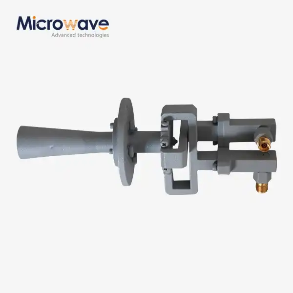
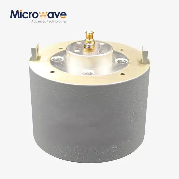
Conical Linear Polarization Horn Antenna
Conical Linear Polarization Horn Antenna for Reflector Feeds & RF Measurement Systems
The Conical Linear Polarization Horn Antenna from Advanced Microwave Technologies (ADM) is built on a conical flare geometry fed by a circular waveguide operating in the dominant TE11 mode. It delivers gain from 15 dBi to 25 dBi, maintains VSWR better than 1.5:1, and produces rotationally symmetric radiation patterns. Manufactured using electroforming or whole-body CNC processing, the antenna is available with circular polarizer combinations and is suited for satellite communication, radar cross-section measurement, and millimeter-wave testing.
What Makes This Conical Linear Polarization Horn Antenna Different?
Unlike pyramidal horn antennas, the conical design uses a circular aperture that naturally produces symmetric E-plane and H-plane beamwidths. This symmetry reduces cross-polarization interference and delivers a cleaner Gaussian beam profile — two characteristics that are particularly relevant when feeding a parabolic reflector or conducting precision RF measurements.
The antenna operates in linear polarization by default. When circular polarization is required, a combination of circular polarizers can be added without replacing the antenna body. This allows a single antenna to support multiple test configurations.
ADM manufactures this antenna using electroforming or whole-body CNC processing. Both methods produce consistent internal throat geometry held to micron-level tolerances.
Key Technical Specifications
Parameter | Specification |
Gain Range | 15 dBi – 25 dBi (typical) |
VSWR | Better than 1.5:1 across operating bandwidth |
Polarization | Linear (circular available with polarizer) |
Feed Mode | TE11 (dominant mode, circular waveguide) |
Example Frequency Band | 18 – 26.5 GHz (K-band); other bands available |
Cross-Polarization Isolation | >25 dB (XPD tested) |
Material | Aluminum or copper alloy |
Surface Treatment | Conductive alodine, silver plating, or gold plating |
Interface | Circular or rectangular waveguide flange |
Measurement Standard | IEEE Standard 149 |
Custom frequency bands and flange configurations are available. Contact ADM for specific requirements.
Materials and Surface Treatment
The antenna body is manufactured from aluminum or copper alloys. Depending on the operating frequency and environment, the interior and exterior surfaces are treated with one of the following options:
· Conductive alodine coating — for standard lab environments
· Silver plating — to reduce ohmic losses at higher microwave frequencies
· Gold plating — recommended for millimeter-wave frequencies where surface resistance is a primary concern
These surface finishes resist oxidation and help maintain stable antenna performance across different operating environments.
Application Scenarios
Reflector Antenna Feeds and Satellite Ground Stations
The symmetric beam pattern of the Conical Linear Polarization Horn Antenna makes it well suited as a primary feed for Cassegrain and Gregorian reflector systems. It has a high lighting efficiency and a low spillover loss, which are both important for radio telescopes and ground stations for satellite transmission.
How to Measure Radar Cross Section (RCS)
The antenna is used as a source antenna for RCS tests inside anechoic chambers. Its stable linear polarisation makes it possible to separate horizontal and vertical scattering matrices accurately when studying materials and aircraft parts.
5G and mmWave EMC / Immunity Testing
The antenna keeps the field level even during high-frequency immunity tests, which are used to test smartphones, IoT devices, and other consumer electronics. Low cross-polar interference helps make sure that test results are always the same and can be repeated.
Quality Control Process
Before sending any unit out, ADM checks it through a structured quality control process.
Electrical Performance Verification
A Vector Network Analyser (VNA) is used to check each antenna's VSWR and return loss across the whole frequency range it works in. For every unit, Cross-Polarization Discrimination (XPD) is measured and written down.
Pattern Measurement in the Far Field
The microwave darkroom that ADM runs is 24 meters long and has an antenna plane near and far field measuring recombination chamber. From 0.5 GHz to 110 GHz, this facility can measure both near-field and far-field patterns. According to IEEE Standard 149, gain calibration is done.
Inspection of Sizes and Surfaces
The internal throat surface roughness is checked to within a few microns. Dimensional inspection is an important part of the production process because flaws in the surface in this area can lead to mode change and unwanted reflections.
Customization and Ordering Options
ADM supports flexible ordering options for B2B customers of Conical Linear Polarization Horn Antenna:
· Frequency band customization across 0.5 GHz to 110 GHz
· Flange type selection: circular waveguide flange, rectangular waveguide flange, or custom interface
· Waveguide-to-Coax Adapter compatibility for SMA, 2.92 mm, and N-type connectors
· Polarization mode: linear standard or circular with polarizer combination
· Surface treatment selection based on frequency range and environmental requirements
If a coaxial connection is required for VNA or signal generator use, a matched Waveguide-to-Coax Adapter is needed. ADM can supply matched adapters together with the antenna.
FAQ
Q: What's the difference between a product and a conical horn?
A: The circular shape of the conical horn's opening makes the E- and H-plane beamwidths symmetric. Because of this, it works better for reflector feeds that need even lighting.
Q: How fast of a connection can I expect?
A: The operating bandwidth is the same as the band that feeds into the circular waveguide. For example, K-band units work the same way from 18 to 26.5 GHz.
Q: How do you keep the clarity of polarisation?
A: The move from a circle to a rectangle is precisely machined, and the feed system keeps cross-polarization isolation above 25 dB. Before being sent out, every unit is checked for XPD.
Q: What kind of adapter do I need to connect to a coaxial system?
A: Yes. A waveguide flange connects the antenna to the waveguide. To connect to SMA, 2.92 mm, or N-type coaxial ports, you need a Waveguide-to-Coax Adapter that is the right size and shape.
Q: Is it possible to change the polarisation mode to circular?
A: Yes. When a circular polariser combination is added to the linear polarisation configuration, the antenna can handle circular polarisation. You can say this when you place your order.
Contact Us
For technical specifications, custom orders, or pricing for the Conical Linear Polarization Horn Antenna, contact our team at craig@admicrowave.com.
YOU MAY LIKE
 VIEW MOREPoint Focusing Horn Lens Antenna
 VIEW MOREFeed Fired Lens Antenna
 VIEW MOREMini Wideband Double-ridged Horn Antenna
 VIEW MOREUltra Double-ridged Horn Antenna
 VIEW MORELadder Membrane Square Dual Circular Polarization Horn Antenna
 VIEW MORELadder Membrane Conical Dual circular Polarization Horn Antenna
 VIEW MOREDual Linear Broadband Dual Circular Polarization Horn Antenna
 VIEW MOREPlanar Spiral Antenna
