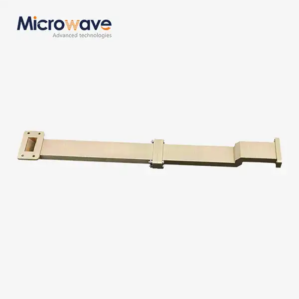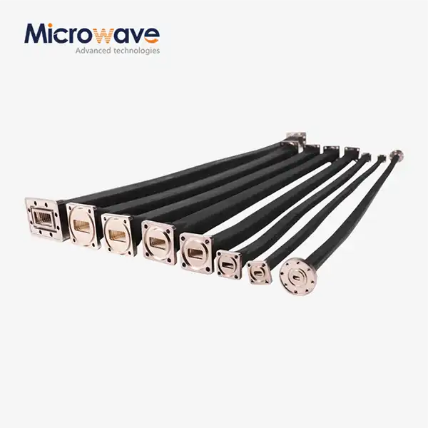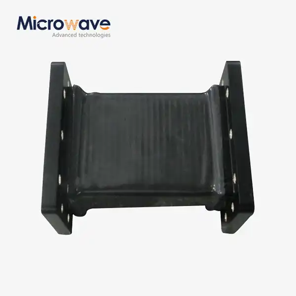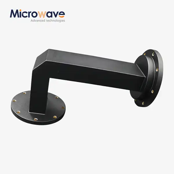
Waveguide Miter Bend
Waveguide Miter Bend for Space-Constrained RF Systems
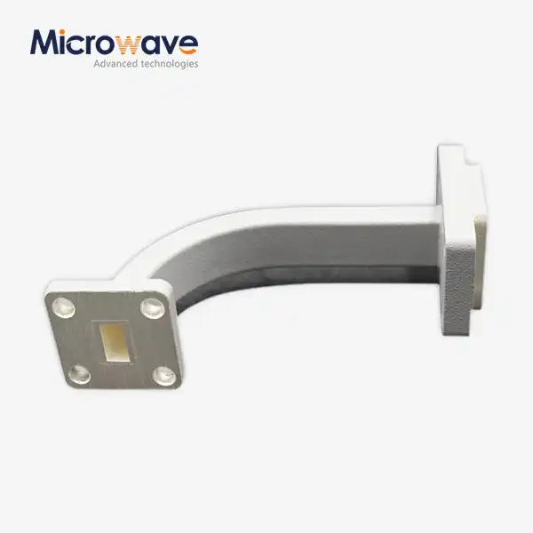
When routing waveguide runs in compact assemblies, a waveguide miter bend offers a sharp 90-degree direction change without the long sweep radius that a conventional curved bend requires. The component uses a 45-degree conductive reflector plane at the corner junction to redirect microwave energy, achieving a near-zero turn radius. Advanced Microwave Technologies Co., Ltd. (ADM) manufactures E-plane and H-plane variants across WR-28 to WR-2300 waveguide sizes, with in-house electrical testing from 0.5 GHz to 110 GHz.
What Is a Waveguide Miter Bend?
A product redirects microwave energy through a precisely angled conductive plane at the corner junction — an optical reflection principle applied to guided wave propagation. The miter geometry produces a much smaller physical footprint than a sweep bend, which relies on a gradual radius to maintain low reflection.
Uncompensated sharp corners introduce a localized capacitive discontinuity. Modern designs address this by incorporating impedance-matching structures — such as inductive steps or tuning posts — directly at the miter point, keeping VSWR low and return loss high across the operating band.
Two standard orientations are available:
· E-Plane Bend — the bend runs along the narrow wall of the waveguide; the electric field vector lies in the plane of the bend
· H-Plane Bend — the bend runs along the wide wall of the waveguide; the magnetic field vector lies in the plane of the bend
The correct orientation depends on your system's field polarization and physical routing constraints. Specifying the wrong plane does not cause immediate failure but will affect the matching network geometry and may shift the VSWR response.
Key Technical Specifications
Parameter | Specification |
Bend Angle | 90° standard; custom angles (30°, 45°, 60°) available |
VSWR | < 1.10:1 over operating bandwidth |
Insertion Loss | < 0.05 dB |
Waveguide Size Range | WR-28 to WR-2300 |
Flange Standard | UG, CPR (per EIA and MIL-DTL-85) |
Available Configurations | E-Plane, H-Plane |
Body Materials | OFHC Copper, Aluminum 6061-T6, Brass |
Internal Surface Finish | Silver or gold plating |
External Surface Finish | Chem-film, paint coating |
Power Handling | High peak and average (CW) power; pressurization supported |
Manufacturing Standards | MIL-DTL-85, EIA |
Materials and Surface Treatment
Oxygen-Free High Conductivity (OFHC) Copper, Aluminium 6061-T6, or Brass are the three main materials that are used to make the bend bodies. Which one you choose affects the weight, electrical conductivity, and unit cost. OFHC Copper has the lowest resistive loss, Aluminium 6061-T6 is lighter, and Brass is best for moderate-frequency uses where cost and ease of machining are important.
Internal surfaces of Waveguide Miter Bend components are finished with silver or gold plating. When the frequency goes above the K-band, the skin depth drops to the point where surface roughness can be used to measure insertion loss. At those frequencies, silver plating followed by a passivation layer gives the best balance of conductivity to oxidation resistance.
For environmental durability in field-deployed or airborne installations, the outside surfaces are treated with a chem-film or paint.
Electrical Performance
The VSWR specification of less than 1.10:1 across the operating band puts this component on the same level as sweep bends in terms of how well it reflects light, but the physical envelope is much smaller. It is possible to get insertion loss below 0.05 dB by using high-conductivity internal plating and very close tolerances when cutting the mitre shape.
When used with high-power microwaves (HPM), the sharp corner can focus the electric field and lower the bar for breakdown. On HPM-rated units, ADM rounds the inside mitre edges. When the peak power is high, it is also suggested to pressurise with dry air or SF6 gas to stop arcing at the corner discontinuity.
Application Scenarios
Airborne Radar Systems
Airborne fire-control radar and fighter jet nose cones need waveguide runs that connect transmitters to antenna arrays in very small spaces. Mitre bends can handle changes in direction without needing large sweep radii, and their small shape works with the structural and vibration limits of airborne platforms.
Industrial Microwave Heating
Large-format waveguides, like the WR-975 that works at 915 MHz or 2.45 GHz, are used in drying and heating lines in factories. When kilowatt-level power loads are present and flexible coaxial cable is not an option, mitre bends allow these waveguides to go around machinery frames and structural columns.
Feed Chains for Satellite Earth Stations
Filters, multiplexers, and amplifiers are crammed into dense equipment racks that make up the uplink and downlink units of a SatCom hub. Mitre bends make it possible for small, directional routing to keep the phase stability and low reflection that are needed for high-throughput satellite links.
Customization and Engineering Support
Standard Waveguide Miter Bend bends at 90° are good for most routing situations, but unique angles of 30°, 45°, 60°, or even more can be made upon request. Each non-standard angle needs its own engineering review. For example, the 45-degree reflector formula used for 90-degree bends doesn't work directly with other angles, and the mitre plane geometry needs to be recalculated to make sure that the impedance matches correctly.
Before production starts, ADM's engineering team looks over customer system layout drawings, makes sure the polarisation vectors are correct, and suggests the best E-plane or H-plane orientation. Electrical testing can be done across ADM's measurement range of 0.5 GHz to 110 GHz for both prototypes and large production runs.
Quality Assurance
Before being sent out, every unit is tested in ADM's own microwave lab. The building has a 24-meter microwave anechoic chamber and the ability to measure both near- and far-fields. This allows for high-precision checks of VSWR, insertion loss, and dimensional conformance. The parts are made according to the MIL-DTL-85 and EIA flange interface standards.
FAQ
Q: What's the difference between a product bend and a sweep bend in real life?
A: A sweep bend has a gradually decreasing radius that keeps reflections low over a large bandwidth without the need for extra matching structures. The sharp corner of a mitre bend, along with impedance-matching features at the break, lets it achieve similar VSWR performance in a much smaller space. If you are limited by space, choose a mitre bend. If you have room and want to make the matched design easier, choose a sweep bend.
Q: How do I choose between E-Plane and H-Plane?
A: It is E-Plane if the bend is along the thin wall of the waveguide. It is H-Plane if it goes along the wide wall. Check the polarisation of the electric field in your system layout drawing before you specify, as the orientation changes the way the bend matches the impedance.
Q: Is it possible for mitre bends to handle strong signals?
A: Yes. For HPM uses, ADM rounds the inside mitre sides to spread out the electric field at the corner less. It is suggested that dry air or SF6 pressurisation be used to raise the breakdown threshold at high peak power levels.
Q: Which finish on the surface is best for K-band and higher?
A: At K-band and above, it is best to use silver metal with a passivation overcoat. At those frequencies, the skin depth isn't very deep, so the quality of the finish has a direct and measured effect on the insertion loss.
Q: Can I get bend angles that aren't shown here?
A: Yes, ADM can make turns at angles of 30°, 45°, 60°, and more. For each, an engineering study is needed to find the right mitre plane geometry for that angle.
Q: What sizes of waveguides can be used?
A: As a general rule, sizes range from WR-28 to WR-2300. In this range, you can find flanges that meet the UG or CPR interface standards set by the EIA and MIL-DTL-85.
Contact Us
Send your waveguide size, frequency range, and bend angle for the Waveguide Miter Bend to craig@admicrowave.com and ADM's engineering team will respond with a recommendation or quote.