Waveguide Calibration Kits
Waveguide Calibration Kits for VNA Measurement — Precision Standards for Millimeter-Wave and Microwave Testing
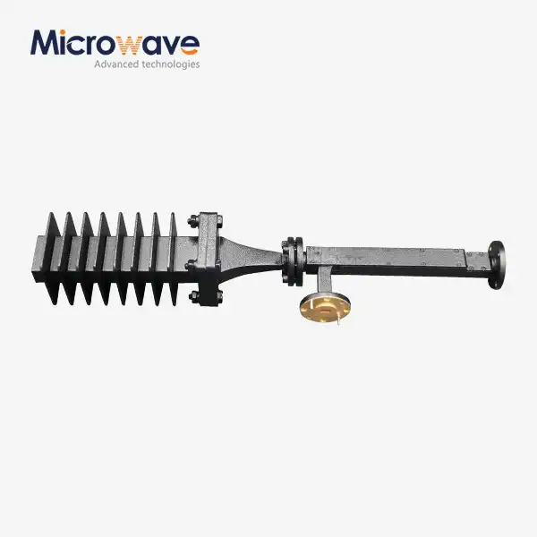
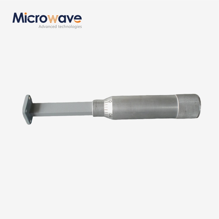
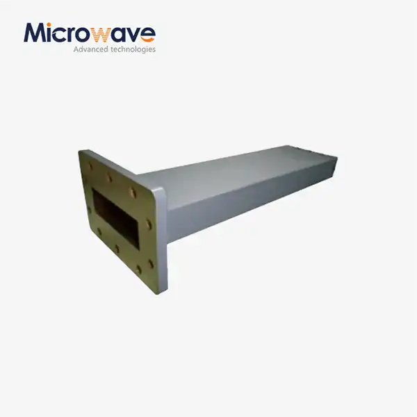
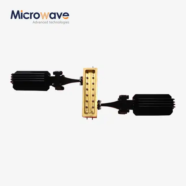
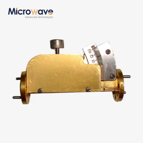
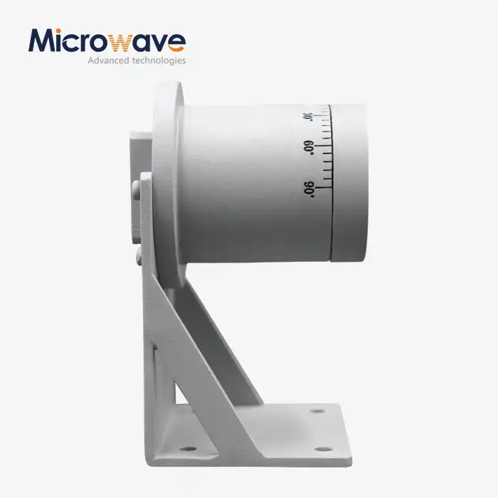
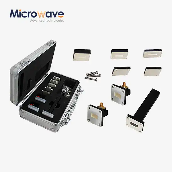
Advanced Microwave Technologies (ADM) designs and manufactures Waveguide Calibration Kits to establish a repeatable measurement reference plane and remove systematic error terms from Vector Network Analyzer measurements. Each kit includes precision Shorts, Offset Shims, Fixed Loads, and Sliding Loads machined from thermally stable alloys, covering frequency bands from WR-90 X-band up to WR-1.0 Terahertz. ADM operates an in-house 24 m Microwave Darkroom with measurement capability from 0.5 GHz to 110 GHz.
What Are Waveguide Calibration Kits?
Unlike coaxial interfaces that propagate TEM modes, waveguide systems carry TE and TM propagation modes inside hollow metallic guides. This difference makes calibration considerably more demanding.
A waveguide calibration kit provides your VNA with a set of known electrical standards — Shorts, Offsets, Matched Loads, and Sliding Loads — so the instrument can calculate and remove directivity errors, source match errors, and frequency response tracking errors from its measurements.
Without proper calibration, flange misalignments, connector repeatability issues, and signal losses will distort your measurement data. These kits address that problem at the measurement plane itself.

Technical Specifications
Parameter | Specification |
Frequency Coverage | WR-90 (X-band) to WR-1.0 (Terahertz bands) |
Return Loss (Fixed Load) | > 40 dB (VSWR < 1.02) |
Phase Accuracy | ± 0.5 degrees |
Flange Flatness Tolerance | Within 0.0003 inches |
Internal Surface Roughness | Better than 10 micro-inches |
Base Materials | Coin Silver, Invar, Tellurium Copper |
Plating | High-purity Gold (Au) or Silver (Ag) |
Supported Calibration Algorithms | TRL, SSLT, Offset Short |
Standards Reference | IEEE P1785, MIL-DTL-3928 |
Environmental Testing Reference | MIL-STD-202 (thermal shock and vibration) |
Material and Construction
Every component starts with a thermally stable base alloy — Coin Silver, Invar, or Tellurium Copper — selected to minimize dimensional drift across temperature changes.
Internal surfaces are held to a roughness better than 10 micro-inches. This level of finish reduces standing waves at high frequencies that would otherwise introduce error into calibration data.
High-purity Gold or Silver plating is applied to all mating surfaces. Gold resists oxidation and reduces skin-effect losses. Silver offers low-loss performance in applications where plating wear from repeated mating cycles is less of a concern. Flange flatness is controlled within 0.0003 inches to prevent air gaps that cause signal leakage at the junction.
Supported Calibration Methods
These waveguide calibration kits support three primary calibration algorithms, each suited to a different measurement scenario.
TRL (Thru-Reflect-Line)
TRL is the preferred method for millimeter-wave and sub-terahertz measurements. Rather than relying on a perfectly matched resistive load, it uses a precision air-line whose characteristic impedance can be machined to higher dimensional accuracy than any resistive termination. This makes TRL the most accurate option at frequencies above 50 GHz.
SSLT (Short-Short-Load-Thru)
SSLT suits broadband applications where two offset short positions are used alongside a load to achieve full two-port error correction across a wide frequency span.
Offset Short
The Offset Short method provides a practical option for single-port reflection measurements where a matched load is not required, reducing kit complexity and cost.
Application Scenarios
Aerospace and Defense
These kits are used to set up measurement ranges for Radar Cross Section and to describe phased array antenna modules that are kept inside anechoic chambers. In this case, it is very important that the dimensions stay the same even when the temperature changes a lot, which is common in field simulation settings.
Satellite Payload Testing
These kits set up the error-correction terms needed to measure insertion loss and group delay of space-flight gear with the accuracy needed for testing satellite transponders in a thermal vacuum chamber.
Automotive Radar Manufacturing
Using these kits for regular system verification helps keep measurements consistent and makes sure that sensors meet their standards on production lines for ADAS collision-avoidance sensors that work at 77 GHz and 79 GHz.
Quality Control Process
Every kit that ADM ships goes through a multi-step inspection process.
The CMM Dimensional Inspection checks the waveguide aperture sizes (a and b dimensions) and the depths of the flange pins. When these measurements are off, they cause step capacitance at the junction, which lowers the accuracy of the calibration.
Visual Surface Inspection looks at each mating flange through a microscope to see if there are any plating flaws, scratches, or surface pits that could lead to RF leakage or passive intermodulation.
The VNA Verification Test compares each kit to an in-house kept reference calibration kit. This test makes sure that any remaining source match and directivity errors are still within the acceptable range, which is usually at or above 35–40 dB effective directivity.
Environmental Stability Testing uses MIL-STD-202 methods for thermal shock and vibration to make sure that the internal termination elements won't move in the field.
Why Work with ADM?
ADM's in-house 24 m Microwave Darkroom and measurement capability from 0.5 GHz to 110 GHz means each Waveguide Calibration Kits is verified in the same environment used to test antenna systems and waveguide assemblies.
ADM has been in the microwave engineering business for more than 20 years and has offices in Xi'an, Chengdu, Beijing, Tianjin, and Shijiazhuang. Standard configurations are available for all of the above frequency ranges. You can talk to the engineering team directly about making custom configurations for waveguides of a certain size or frequency needs.
Every kit comes with precision alignment dowels to make sure that the flanges don't get out of line when they are being mated. Each kit comes with paperwork that meets the standards for traceability.
FAQ
Q: When should I use a Sliding Load instead of a Fixed Load?
A: A sliding load is useful in low-frequency bands or broadband settings where it's hard to get a steady load that works well. The VNA can mathematically separate coupler directivity from residual load reflection thanks to the sliding mechanism. When speed and ease of use are the most important things, fixed loads work best in high-throughput areas.
Q: Can I mix different types of flanges, like UG-387/U and UG-387/U-Mod?
A: You shouldn't mix types of flanges unless you have precision alignment pins. Even small misalignments of the aperture cause reflections that move the calibration plane. Precision alignment dowels are included in ADM kits, and using standards from different companies could affect the accuracy of the measurements.
Q: How often should these kits be checked again?
A: A period of 12 months is normal. A 6-month cycle is usual in high-volume production settings like making radars for cars, since repeated mating cycles wear down the plating surfaces mechanically.
Q: Why does the torque of a connection matter?
A: When you over-torque, the flange surface deforms and air gaps form that won't go away. Poor electrical contact and unreliable phase readings are caused by under-torquing. Always use a torque wrench that is set to the right size for the flange screw.
Q: What range of frequencies do ADM's kits cover?
A: ADM's kits cover bands from WR-90 X-band to WR-1.0 Terahertz. Custom configurations are possible for waveguides of certain sizes and frequency ranges; contact ADM to talk about your needs.