





BLOG
Straight Waveguide for Microwave Systems: Performance Factors
August 3, 2026
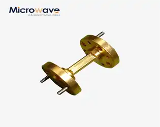
Straight waveguides represent the backbone of modern microwave transmission systems, functioning as precision-engineered conduits that channel electromagnetic energy with remarkable efficiency. These metallic structures—predominantly crafted from copper or aluminum alloys—enable the low-loss propagation of signals across frequencies ranging from several gigahertz to millimeter-wave bands exceeding 110 GHz. Understanding the performance variables governing waveguide operation empowers procurement teams and system designers to specify components that deliver optimal signal integrity, power handling, and long-term reliability in demanding aerospace, satellite, and telecommunications environments.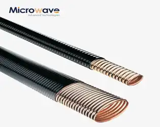
Why Elliptical Microwave Waveguides Beat Rigid in Long-Haul Runs?
July 31, 2026
When it comes to sending microwaves over long distances, elliptical microwave waveguides do what fixed rectangular and circular waveguides often can't: they allow for flexible paths with little signal loss. Their corrugated elliptical cross-section strikes a perfect balance between being able to bend mechanically and being electromagnetically efficient. This means that you don't need to use multiple flange connections or complicated elbow assemblies, which can cause reflection losses and VSWR degradation. This design benefit directly means fewer installation points, lower upkeep costs, and signal stability that stays the same across tower runs, satellite uplinks, and high-frequency backhaul systems. This mix of performance and usefulness is a clear benefit for procurement teams that are in charge of mission-critical infrastructure.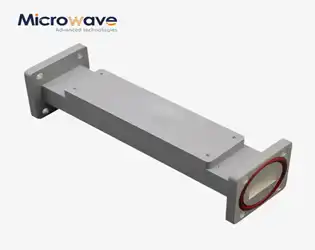
Microwave Bandpass Filter Applications in RF Systems
July 31, 2026
Microwave bandpass filters play an indispensable role in modern RF systems, enabling precise frequency selection and signal integrity across telecommunications, aerospace, defense, and scientific research. Among the various filter architectures available, WG bandpass filters stand out by leveraging waveguide technology to deliver exceptional performance in high-frequency and high-power environments. These filters allow only desired frequency bands to pass while rejecting unwanted signals, making them critical for applications ranging from satellite communications to radar systems where signal purity directly impacts operational effectiveness.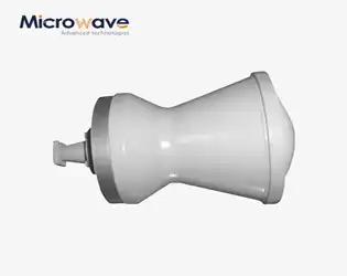
Horn Lens Antenna Gain Optimization for RF Applications
July 31, 2026
Horn lens antenna gain optimization is essential for maximizing the efficiency and range of RF communication systems. The horn lens antenna combines a feed horn with a dielectric or shaped lens structure to focus electromagnetic energy into a narrow beam, thereby increasing directional gain. Optimizing this gain involves careful selection of low-loss materials, precise lens geometry, and accurate feed alignment to minimize signal attenuation and reflection losses. Engineers working with satellite communications, radar systems, and wireless backhaul applications rely on these techniques to achieve the high-performance standards demanded by mission-critical operations, ensuring reliable signal transmission across extended distances.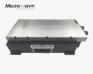
Precision AC Signal Amplifier Selection Considerations
July 30, 2026
Selecting the right AC signal amplifier demands careful technical assessment and an understanding of how amplification systems integrate into mission-critical RF and microwave applications. Whether your organization develops satellite ground systems, aerospace communication platforms, or precision instrumentation, an amplifier's performance directly influences signal fidelity, system reliability, and operational efficiency. This guide clarifies the technical specifications, compatibility requirements, and evaluation frameworks that procurement teams need to make informed decisions aligned with their specific application demands.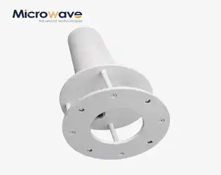
Quadrifilar Helix Antenna Design and Performance Guide
July 30, 2026
When sourcing advanced antenna solutions for mission-critical communication systems, quadrifilar helix antennas consistently emerge as a preferred choice among procurement engineers and technical teams. These specialized antennas deliver exceptional circular polarization, omnidirectional coverage, and robust signal integrity—qualities essential for satellite communications, GPS navigation, LTE networks, and aerospace applications. Understanding their design principles, performance characteristics, and procurement considerations empowers B2B buyers to make informed decisions that align with stringent technical requirements and operational objectives.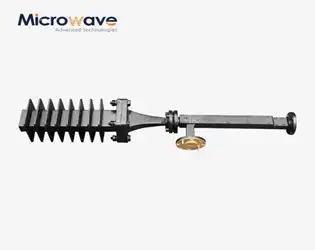
Fixed Attenuator Power Rating Explained for Microwave Design
July 30, 2026
A microwave fixed attenuator serves as a precision component that reduces RF signal strength by a predetermined amount while maintaining signal integrity throughout microwave and millimeter-wave systems. Power rating defines the maximum continuous or peak power level the device can safely handle without thermal damage or performance degradation. Understanding this specification proves essential when designing radar front-ends, satellite ground stations, or aerospace communication links where component failure could compromise mission-critical operations. Selecting attenuators with appropriate power ratings ensures system longevity and prevents costly downtime across defense, telecom, and research applications.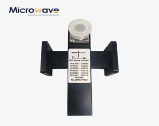
Crossguide Coupler for Waveguide Systems: Design Insights
July 29, 2026
A crossguide coupler represents a specialized directional coupling device that extracts or injects signals within waveguide transmission systems with exceptional precision. These components enable engineers to monitor signal power, measure reflected energy, and split signals across perpendicular waveguide planes while maintaining excellent isolation characteristics. Unlike conventional side-wall couplers, crossguide designs position coupling apertures strategically to achieve broadband performance and superior directivity, making them indispensable in satellite ground stations, radar systems, and high-frequency measurement equipment where signal integrity cannot be compromised.
