


BLOG

Waveguide Terminator Performance and Power Handling Explained
June 29, 2026
Some inactive parts, called waveguide terminators, are very important. Their job is to soak up the electromagnetic energy that moves through RF and microwave waveguide systems. Its main job is to stop signal echoes that aren't needed and could make the system less stable, mess up measures, or damage sensitive gear. Things that are carefully picked out to take microwave energy turn it into heat. The most energy is lost, and the least amount is brought back into the system in this way. People who buy parts for defence, aerospace, satellite communications, and industry R&D need to know how they work at different power levels so they can choose the best one for mission-critical uses.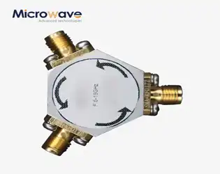
Broadband Circulator Performance in Wideband Microwave Systems
June 29, 2026
When designing modern RF architectures, engineers face a persistent challenge: how to efficiently route high-frequency signals across multiple octaves while maintaining signal integrity and system protection. A broadband circulator addresses this challenge by providing non-reciprocal signal routing over wide frequency ranges, effectively isolating sensitive components from reflected power and enabling simultaneous transmit-receive operations. Unlike narrowband devices limited to specific frequencies, these components utilize advanced ferrite material compositions and precision impedance matching to deliver consistent performance from DC to 40 GHz, making them indispensable in radar, satellite communication, and 5G infrastructure, where frequency agility and system reliability are non-negotiable.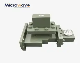
E-Plane Tee Applications in Waveguide Distribution Networks
June 26, 2026
E-Plane Tee components serve as foundational elements in waveguide distribution networks, enabling precise signal splitting and combining with inherent 180-degree phase relationships. These three-port junctions align the auxiliary arm parallel to the electric field plane, making them indispensable for radar tracking systems, satellite ground stations, and high-power microwave applications where phase-dependent signal processing determines system accuracy. Their robust mechanical construction and exceptional power-handling capabilities address critical challenges in defence, aerospace, and telecommunications infrastructure.
Slotted Waveguide Array Antenna Design Considerations Explained
June 26, 2026
When designing high-performance communication systems, understanding the nuances of antenna technology becomes paramount. Slotted waveguide array antennas represent a sophisticated solution where precision engineering meets electromagnetic theory. These devices utilise carefully machined slots in metallic waveguide structures to radiate signals with exceptional control over beam characteristics. Unlike conventional antenna systems relying on separate feed networks, the waveguide itself serves dual purposes—transmitting microwave energy internally and radiating it externally through optimised apertures. This integrated approach dramatically reduces insertion losses, making these antennas indispensable for defence radar installations, satellite ground terminals, and maritime surveillance where signal integrity directly impacts mission success.
Why are high-power waveguide isolators critical in High-Power RF?
June 26, 2026
High-power waveguide isolators are necessary safety barriers in modern RF systems. They stop catastrophic equipment failure by collecting reflected energy that would have hurt sensitive emitters otherwise. These non-reciprocal devices, which are made up of carefully designed ferrite cores and permanent magnets inside waveguide housings, make sure that signals only flow in one direction and turn reverse power into heat that can be controlled. In mission-critical settings like radar sites, satellite ground stations, and defence communication networks, their ability to keep signals intact at kilowatt to megawatt power levels is a direct factor in determining system efficiency, operational safety, and the long-term dependability of the equipment.
How Does an E-Plane Tee Split Microwave Signals Efficiently?
June 25, 2026
The E-Plane Tee is one of the most important waveguide parts in modern microwave engineering. It divides electromagnetic signals very well and lets you manage their phase very well. This three-port junction, which is also called a "series tee," makes the phase difference between the output signals 180 degrees. This makes it essential for tasks that need accurate signal reduction and processing that depends on phase. When purchasing, engineers and technical buying teams have to choose high-frequency components; they need to know how this device works and why it's better than other options in some situations. This is important for making sure that the system is reliable and performs well. In the military, aircraft, satellite communications, and telecommunications industries, this guide is useful for purchase managers, RF experts, and system designers. We look at the basic ideas behind how they work, compare their performance to other parts, and look at real-life situations where these gadgets provide measured benefits. We give your company more than just technical specs; we also give you practical buying strategies to help you find approved, high-performance waveguide components that meet the strict requirements of mission-critical systems. When you're done with this guide, you'll know enough to confidently make purchases that improve both signal accuracy and operating efficiency.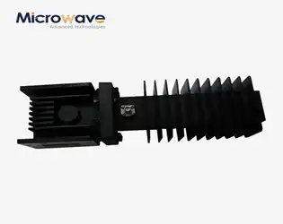
How Do High Power Waveguide Isolators Protect RF Systems?
June 25, 2026
High-power waveguide isolators keep RF systems safe by letting signals travel in only one way and soaking up reflected energy that could hurt microwave sources that are sensitive. These passive, non-reciprocal devices use ferrite materials inside a waveguide housing that is pushed in one direction by permanent magnets to allow forward signals to pass with little insertion loss and stop reverse-traveling echoes into matching loads. Isolators stop impedance mismatch reflections from reaching power amplifiers, magnetrons, klystrons, and solid-state devices. This stops voltage standing wave ratio (VSWR) spikes, lowers frequency pulling, and protects against catastrophic component failure. This is why they are essential for mission-critical radar, satellite communications, and test equipment.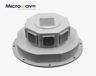
How Does a Slotted Waveguide Array Antenna Improve Radar Performance?
June 25, 2026
A slotted waveguide array antenna changes the way radar works by using carefully made holes in a metal waveguide structure to send out electromagnetic energy very precisely. This design doesn't have feed network losses like microstrip or patch antennas because the waveguide acts as both a transmission line and a shield. The slots work as magnetic dipoles to make high-gain radiation patterns that can be predicted and are needed for radar systems. This design handles power better, which is important for long-range sensing, and it keeps a low profile, which is perfect for aircraft and marine uses where sturdiness and thermal economy are key.
