Measuring VSWR Accurately with a Coaxial Directional Coupler
When engineers need to verify signal integrity in an RF system, VSWR measurement is one of the first diagnostics they run. A coaxial directional coupler gives you a clean, non-intrusive way to sample forward and reflected power simultaneously — without breaking the main signal path. At ADM, we've worked with defense contractors, satellite integrators, and R&D labs for over two decades, and this method consistently delivers the most reliable VSWR data across demanding frequency bands.
Understanding VSWR and Its Measurement Challenges
What VSWR Actually Tells You
The Voltage Standing Wave Ratio (VSWR) measures how different a source's and load's impedances are. It is 1:1 for a perfect match. In real life, numbers higher than 1.5:1 can cause a lot of power to be reflected, which lowers the efficiency of the system and could even damage the emitter stages. IEEE standards say that even a 2:1 VSWR returns about 11% of the power that is sent. This is a very important number in high-power radar or satellite transfer chains.
Why Traditional Methods Fall Short
Older ways of measuring, like inline wattmeters, slotted lines, and basic reflectometers, introduce their own insertion loss and can give wrong readings when the test setup itself makes reflections. The data is messed up before it gets to the engineer because of an impedance mismatch in the measuring tool. When used in broad or pulsed-RF settings, these tools don't have the frequency range and dynamic range they need to make accurate diagnoses.
How Directional Sampling Changes the Picture
With high isolation, a well-designed directional coupler divides waves that come in and waves that bounce back, giving you two clean signals to compare. The key to accuracy is this space between them. You're not measuring a single standing wave, but separate forward and backward power samples. This is a much more accurate way than the old slotted-line methods, which can't be used above a few gigahertz.
Technical Principles of Coaxial Directional Couplers
Signal Separation Through Electromagnetic Coupling
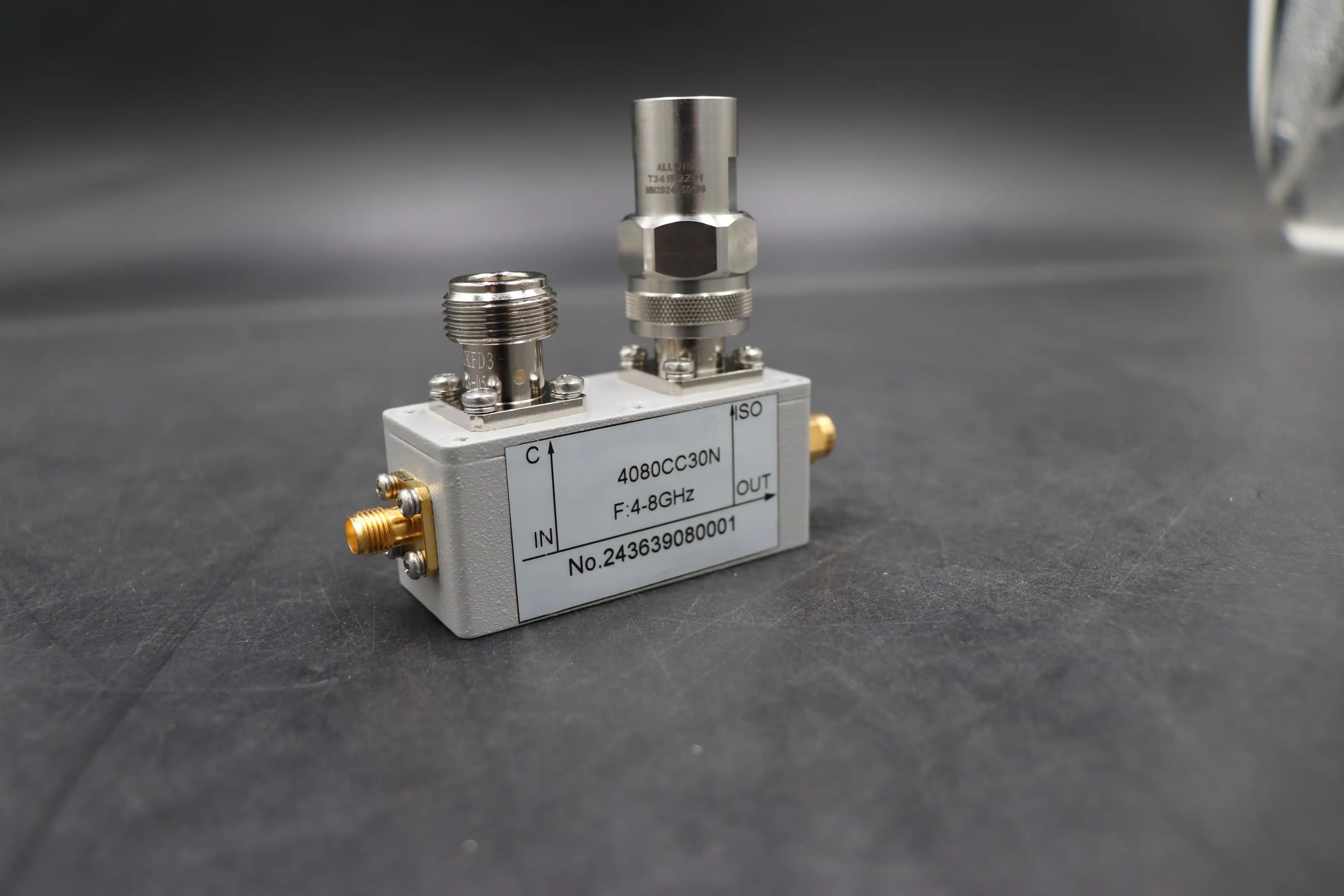
Controlled electromagnetic coupling between a main transmission line and a secondary linked line inside a precision coaxial body is what the core process is based on. A small amount of the signal's energy is sent to the secondary port when it goes through the main line. Importantly, the coupler's shape makes sure that only waves moving forward or backward can couple to certain ports. This gives you direction selection.
Key Specifications That Drive Accuracy
Four factors tell you if a coupler is right for your VSWR testing needs. In real life, these are the specifications that matter the most:
- Coupling Factor (6 dB to 40 dB): Determines what fraction of power is sampled. Lower values (tighter coupling) suit low-power signals; higher values protect sensitive detectors in high-power transmitter chains.
- Directivity (>20 dB, ideally >30 dB): The most critical quality metric. High directivity means the coupler cleanly differentiates forward from reflected signals, directly reducing measurement error in return loss calculations.
- Insertion Loss (<0.5 dB typical): The main-line signal should pass through with minimal attenuation. Lower insertion loss preserves system efficiency during in-line monitoring.
- Port VSWR (<1.25:1 typical): A coupler with poor port match introduces its own reflections, corrupting the measurement it's supposed to provide.
These four factors work together. Even if a coupler has great directivity but bad port VSWR, the VSWR numbers will still be off. When reading a datasheet, you should always look at them together.
Frequency Range and Waveform Compatibility
Coaxial directional couplers typically cover frequency ranges from 0.5 GHz to 18 GHz in normal catalog setups, with specialty versions going up to 40 GHz and beyond. We can test coupler performance in a wide range of modern RF applications, from L-band satellite links to millimeter-wave radar systems, because ADM's measurement lab has equipment that can work up to 110 GHz.
Choosing the Right Coaxial Directional Coupler for Your VSWR Measurements
Matching the Coupler to Your Frequency and Power Requirements
Start with the frequency band you want to use. When it comes to shape, a coupler made for X-band (8–12 GHz) radar testing will be different from one made for Ku-band satellite links. Second, make sure that the continuous wave (CW) power level is higher than your peak working power by a safe amount, usually at least 3 dB. Mismatched power levels are a common mistake in the buying process that causes devices to fail early in the field.
Coaxial vs. Other Coupler Architectures
Coaxial directional couplers are better for bench testing, system integration, and field deployment because they connect directly into standard 50-ohm coaxial chains using SMA, N-type, or TNC connectors without the need for extra transition hardware. Stripline and hybrid couplers work well in fixed PCB-integrated designs. This makes setting up the test easier and gets rid of the extra reflection sources that connector adapters add.
Balancing Directivity, Insertion Loss, and Cost
It is a simple trade-off that more directivity costs more. A coupler with >30 dB directivity is worth the extra money if you need to measure VSWR in a lab and be accurate within ±0.5 dB for return loss. For checking the "go" or "no-go" of a production line, a unit with 20 dB directivity usually gives enough accuracy at a lower cost per unit. Setting the level of error you need in your measurements before you buy them keeps you from over-specifying and spending too much money on things that aren't necessary.
Practical Applications and Case Studies
RF Antenna Testing and Transmitter Monitoring
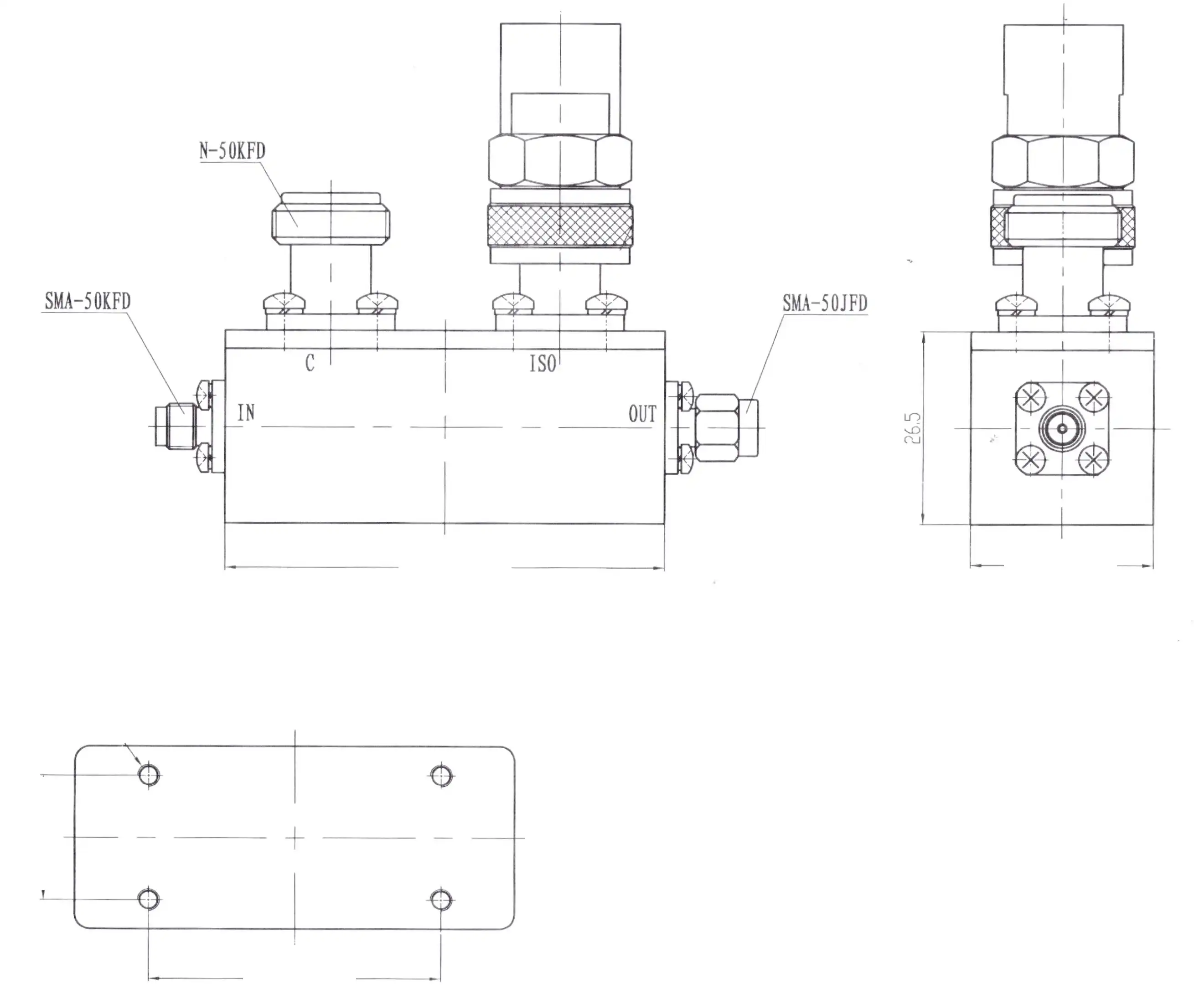
In antenna test ranges, like ADM's own 24-meter microwave darkroom that works from 0.5 to 110 GHz, directional couplers connect the signal ports that receive and reflect signals. This lets the reflectometer do continuous return loss sweeps across the antenna's operating band. With this method, resonant mismatches, connector flaws, and feed network anomalies can be found with a higher frequency precision than with spot readings.
Defense and Aerospace Deployment Example
A company that builds defense radars needed to keep an eye on the VSWR across a chain of high-power X-band transmitters that were working at top pulse powers of more than 1 kW. The engineering team set up an automatic level control loop that corrected output power in real time while also recording reflected power data. This was done by installing a 40 dB coaxial directional coupler that was rated for the required peak power at the transmitter output. It was possible to see a drop in transmitter safety trips and an increase in radar availability without adding a high-loss measuring device to the main RF line.
Vector Network Analyzer Extension for R&D Labs
Researchers often connect directional couplers to VNA test ports to make measurements possible beyond the front panel of the analyzer. In this setup, the coupler works as a remote signal sampling point. This lets engineers test devices like amplifiers, filters, and antenna feeds where they are actually mounted, instead of at the end of a long test wire, which would introduce its own reflection mistakes.
Procurement Insights: Where and How to Source Quality Directional Couplers
Evaluating Suppliers Before You Commit
Ask for full datasheets that show measured, not just average, values for port VSWR, directivity, and insertion loss across the whole frequency range you've given. If a supplier only gives you "typical" specs without measurement data, you won't know what the exact specs are at the edges of the band, which is where most system designs put the most stress on margins. Every part that is meant for use in defense or satellites should come with ISO 9001 approval and paperwork showing that it meets RoHS requirements.
Pricing, Lead Times, and Custom Configurations
Prices for standard coaxial directional couplers in catalogs for frequencies up to 18 GHz run from a few hundred to several hundred USD per unit, based on the coupling factor and power rating. Lead times are longer for custom setups like larger frequency bands, non-standard coupling values, and ruggedized housings. They are usually 4 to 8 weeks. ADM offers fast OEM prototyping, which lets engineering teams test custom coupler designs before committing to large-scale production.
Conclusion
How well you can measure VSWR depends on how good the directional device is in your test chain. You can trust the data that comes from a coaxial directional coupler with high directivity, low insertion loss, and a proven port VSWR. This trust helps you make better decisions about system dependability. The correct directional coupler is very important when describing an antenna array, keeping an eye on a radar transmitter, or doing production acceptance tests. It separates accurate data from data that isn't clear. ADM sells proven, ISO 9001-certified parts that are backed by 20 years of experience in RF engineering.
FAQ
How does directivity affect my VSWR measurement accuracy?
Directivity sets the floor on your measurement error. A coupler with 20 dB directivity introduces a worst-case return loss error of approximately ±1.7 dB at low VSWR values. Stepping up to 30 dB directivity cuts that error to roughly ±0.6 dB — a meaningful improvement when you're characterizing well-matched antennas or low-reflection amplifier outputs.
What frequency range should I choose for my application?
Select a coupler whose specified frequency range covers your operating band with at least 10% margin on each end. If your system operates from 8 to 10 GHz, a coupler specified for 6 to 12 GHz gives you consistent directivity across your actual operating window rather than relying on edge-of-band performance where directivity often degrades.
Can one coupler handle both high-power and low-power measurements?
A single coupler can span a wide dynamic range if its power rating exceeds your maximum operating power and the coupled port connects to a detector or power meter with sufficient sensitivity at low power levels. Choosing a coupling factor between 20 dB and 30 dB typically covers most lab and field measurement scenarios without requiring separate high-power and low-power hardware.
Partner with ADM for Precision Directional Coupler Solutions
ADM sells coaxial directional couplers that are ISO 9001-certified and made to meet the high accuracy needs of defense, satellite, and R&D uses. We have been making coaxial directional couplers for a long time and can make both standard and custom designs. We also offer full datasheet support and OEM prototyping services. To get specs or a quote, email our tech team at craig@admicrowave.com.
References
1. Pozar, D. M. Microwave Engineering, 4th ed. — Wiley, 2011.
2. IEEE Standard 1785 — IEEE Standard for Rectangular Metallic Waveguides and Their Interfaces for Frequencies of 110 GHz and Above — IEEE, 2012.
3. Collin, R. E. Foundations for Microwave Engineering, 2nd ed. — IEEE Press/Wiley, 2001.
4. Agilent Technologies. Applying the 8510 TRL Calibration for Non-Coaxial Measurements — Application Note 8510-8, Agilent Technologies, 2006.
5. Keysight Technologies. Understanding VNA Calibration — Application Note 5989-5765EN, Keysight Technologies, 2014.
6. Montgomery, C. G., Dicke, R. H., and Purcell, E. M. Principles of Microwave Circuits — MIT Radiation Laboratory Series, McGraw-Hill, 1948.