How VSWR Targets Shape Termination Waveguide Absorber Geometry
When engineers ask me why their radar system is showing instability or why a power amplifier keeps failing, the answer often traces back to one number: VSWR. Voltage Standing Wave Ratio is not just a spec on a datasheet — it is the physical signature of how well your system manages reflected energy. And when it comes to termination waveguide absorbers, that number directly dictates how the absorber must be shaped, sized, and loaded with material. Getting this geometry right is the difference between a system that runs reliably for years and one that fails under thermal stress.
Understanding VSWR and Its Influence on Termination Waveguide Performance
VSWR is a way to find the ratio of a transmission line's highest and lowest voltage amplitudes. If everything is right, the VSWR is 1.00:1. In real systems, a VSWR of 1.15:1 means that about 0.5% of the power is reflected back toward the source. This isn't a big deal for low-power lab work, but it could be bad for high-power radar or satellite transmission uses. This mirrored energy is taken away by a terminal waveguide absorber, which turns it into heat before it can hurt the source.
Why Reflection Matters in High-Frequency Systems
When TWTAs, SSPAs, or magnetrons are used in a system, reflected power can pull the frequency, cause arcing, and damage parts permanently. In pulse-mode radar operations, even small reflection coefficients add up over time, which speeds up the wear and tear on hardware.
The Physics Behind Standing Waves
When forward and reflected waves hit each other, they create standing waves. The distance between peaks changes with wavelength, so higher frequencies make the standing wave intervals shorter and the geometric tolerances inside the absorber structure tighter.
VSWR Targets by Application Class
VSWR should be less than 1.05:1 for precision metrology and calibration setups, up to 1.15:1 for high-power industrial and defense-grade systems, and within 1.20:1 for commercial telecom applications. Each of these uses a different absorber geometry to reach its goal.
Key Geometrical Factors of Termination Waveguide Absorbers Influenced by VSWR Targets
The shape of an absorber is not chosen at random. The curve angle, the length-to-aperture ratio, and the placement of the lossy material are all directly related to the VSWR requirement. When I look at how the shape of absorbers changes from one product line to the next, I can see a clear pattern: structures that are longer and more gradual are needed for targets with lower VSWR.
When engineers try to match impedance, they usually use a tapered geometry. Instead of having a sharp edge that reflects energy, a gradual taper changes the impedance of the wave over many wavelengths. According to a study released in IEEE Transactions on Microwave Theory and Techniques, you need a taper length of at least three bands to get VSWR below 1.10:1 over a wide frequency range.
These are the main geometric factors that purchase experts should look at:
- Taper length and angle: Longer, shallower tapers reduce reflection across wider bandwidths. A short, steep taper may hit VSWR targets at a center frequency but fail at band edges.
- Absorber material placement: Carbon-impregnated wedges or silicon carbide (SiC) ceramics positioned at the taper tip absorb the initial wave energy, reducing what reaches the back wall. Material density and loss tangent must align with the target frequency band.
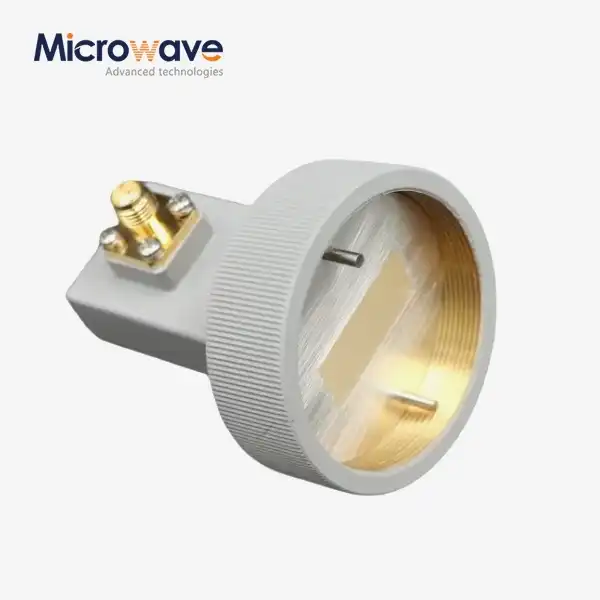
- Waveguide mode considerations: Single-mode rectangular termination waveguides allow simpler taper profiles. Circular waveguides, which support dual polarizations, require rotationally symmetric absorber geometries to handle both polarization modes without generating cross-mode reflections.
All of these things together tell us if a certain absorber geometry can hit the goal VSWR while keeping the thermal load within safe working limits.
Comparative Analysis: Termination Waveguide Absorber Geometries Across Applications
VSWR floors are set by different sectors, and the shape of the absorber is based on those floors. Someone working on a defense radar program in the X band needs a structure that is very different from someone building a commercial Ka-band ground station that runs at tens of watts continuous wave.
Defense and Radar Systems
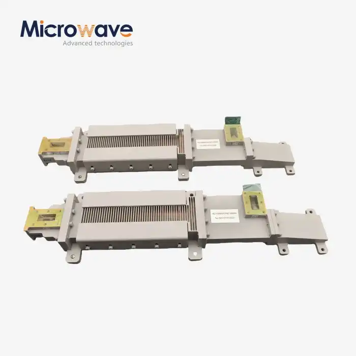
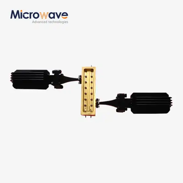
For high-power radar emitter security, VSWR below 1.10:1 and thermal endurance are needed. The absorbers in this case have long SiC tapers and housings that are cooled by air or water. The shape is stretched out and often takes up several guide wavelengths to make sure that the impedance changes slowly in both continuous wave (CW) and pulsed conditions.
Satellite Ground Station Uplinks
To protect SATCOM high-power amplifiers, circulators send reflected energy to a waveguide load. These loads have to deal with changing power levels that happen when antennas aren't lined up right or when bad weather causes beam confusion. In this type of application, standard absorber shapes are small but able to handle heat, often with convective fins.
Research and Instrumentation
When measuring in a lab, VSWR precision is more important than power control. VSWR below 1.05:1 can be achieved with short, precisely machined low-power absorbers that use carbon-impregnated dielectrics and don't cause much heat worry. The shape is small, and the flange must work with normal CPR or UG-cover connections. This is a key condition for buying.
Procurement and Selection: Choosing Termination Waveguides Based on VSWR Considerations
To choose the best waveguide absorber load for a system, you need to carefully look at a number of factors that affect each other. I've seen buying teams focus too much on the VSWR specification and miss important temperature or size restrictions that make integration fail.
The list of things to check should include VSWR over the whole operating frequency range, not just the center frequency; average and peak power ratings; compatibility with cooling methods; flange type and waveguide standard; and the temperature range from which the device can be used. Traceability documentation and ISO 9001 certification from the supplier are musts for high-reliability programs.
Standard stock items work well for popular waveguide bands like WR-90, WR-62, WR-42, and others, and their VSWR performance has already been checked. When the application needs non-standard frequency ranges, power density requirements, or technical limitations, custom-engineered solutions are needed. ADM supports both routes by providing catalog goods with full datasheet paperwork and custom OEM engineering with the ability to quickly turn around prototypes.
Installation, Testing, and Long-Term Performance of Termination Waveguide Absorbers
If you don't place an absorber properly, even one that is well-designed won't work well. When there are mistakes in the alignment of the flanges, air gaps form that cause reflection spots that are not affected by the shape of the absorber. This defeats the intended VSWR performance. It's important to follow the torque specs for flange bolts. Joints that aren't torqued enough leak, and joints that are torqued too much bend the termination waveguide opening.
The standard way to check is to use a vector network analyzer (VNA) to test the VSWR after installation. IEEE Standard 287 gives instructions on how to measure VSWR in connectors and waveguides. If the reading isn't in the range given after installation, it means that either the flange is broken or the absorber element is physically damaged.
Thermal Cycling and Long-Term Degradation
The resistive properties of carbon or clay absorption materials change over time when they are heated and cooled many times. The most common way for a high-power device to fail is for the absorber wedge to crack from thermal shock. This can be seen in VNA measurements as a sudden rise in VSWR.
Maintenance and Requalification Intervals
As long as the system stays within its rated temperature range, the absorbers can last for decades. But VSWR requalification should be done on a regular basis, especially after system power changes or being exposed to the environment. This is good engineering practice. For security and SATCOM uses, requalification should happen every three to five years at the very least.
Signs of Absorber Failure
If the observed VSWR goes above the rated value, the source's working temperature goes up for no apparent reason, or there is obvious flange corrosion, it is clear that the absorber needs to be inspected or replaced before the next operational cycle.
Conclusion
VSWR targets are more than just electrical specs; they are also the engineering brief that determines the shape of the absorber taper, the material choice, the thermal architecture, and the size and weight of the device. Tighter VSWR needs longer tapers, materials with higher loss, and more accurate manufacturing tolerances. The shape of the absorber also needs to match the termination waveguide mode structure, power class, and cooling method that are used in that particular application. Finding the right absorber geometry for your VSWR goal is important for long-term system stability and source protection, no matter if you are looking for it for a military radar program, a SATCOM ground station, or a precision measurement system.
FAQ
What VSWR value should I specify for a high-power radar termination load?
For high-power pulsed radar applications, specify VSWR below 1.10:1 across the full operating bandwidth. Metrology-grade applications require below 1.05:1. Always verify this spec at band edges, not just the center frequency.
Why does taper length affect broadband VSWR performance?
A longer taper transitions impedance gradually over more wavelengths, reducing reflections across a wider frequency range. Short tapers can hit narrow-band VSWR targets but tend to degrade at band edges where the impedance transition is less smooth.
How do I know if my absorber geometry suits a circular waveguide?
Circular waveguide absorbers need rotationally symmetric geometry to handle dual polarizations without exciting cross-mode reflections. Confirm with your supplier that the absorber design accounts for the specific mode set of your circular waveguide band.
Can I use an air-cooled termination load in a liquid-cooled system?
No. High-power liquid-cooled systems operate at power densities that convective air cooling cannot safely manage. Using an air-cooled load in such a system will cause rapid thermal failure of the absorber material.
What documentation should I request when sourcing waveguide absorbers?
Request VNA-measured VSWR data across the full frequency band, power rating certificates, material traceability records, and ISO 9001 certification. For defense programs, also request RoHS compliance documentation and any applicable MIL-spec test reports.
Request a Custom Termination Waveguide Quote from ADM
Advanced Microwave Technologies Co., Ltd. (ADM) is a reliable company that has been making termination waveguides for over 20 years and has quality methods that are ISO 9001-certified. ADM can provide tested performance backed by full datasheet documentation, whether you need standard absorber loads or OEM-engineered solutions that are optimized for specific VSWR targets. You can email our engineering team at craig@admicrowave.com to get a datasheet, a sample, or a quote for buying in bulk.
References
1. Pozar, D. M. — Microwave Engineering, 4th Edition. Wiley, 2011.
2. IEEE Transactions on Microwave Theory and Techniques — "Broadband Waveguide Termination Design Using Tapered Resistive Loads." IEEE, 2008.
3. Collin, R. E. — Foundations for Microwave Engineering, 2nd Edition. Wiley-IEEE Press, 2001.
4. IEEE Standard 287-2007 — Standard for Precision Coaxial Connectors (DC to 110 GHz). IEEE, 2007.
5. Wadell, B. C. — Transmission Line Design Handbook. Artech House, 1991.
6. Montgomery, C. G., Dicke, R. H., and Purcell, E. M. — Principles of Microwave Circuits, MIT Radiation Laboratory Series Vol. 8. McGraw-Hill, 1948.