Low Insertion Loss High Power Coaxial Switches: Benefits and Uses
Choosing the right switching component is very important when making RF systems for defense radar, satellite ground stations, or radio receivers. It can make or break the system's ability to meet mission-critical dependability standards. A high power coaxial switch designed for low insertion loss is the core of precise signal switching. It makes it possible to switch between send and receive lines without any problems, even when the power level is very high. These special devices can handle power levels ranging from hundreds of watts to multiple kilowatts without heating failure, arcing, or impedance problems. This is something that regular RF switches can't do in harsh operating conditions where performance errors are very small.
Understanding Low Insertion Loss High Power Coaxial Switches
What Defines a High Power Coaxial Switch?
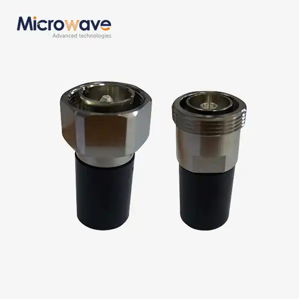
A high power coaxial switch is different from regular RF switches because it can handle high amounts of continuous wave (CW) and peak power without damaging the structure or electrical integrity. Standard switches can handle milliwatts to a few watts of power. High power coaxial switches, on the other hand, are made to handle signals that carry hundreds of watts constantly or spikes at the megawatt level in radar uses. Advanced internal shapes, strong contact materials like gold-plated beryllium copper, and carefully designed dielectric space that stops voltage breakdown and corona discharge make this possible. These devices usually have ruggedized connection ports (7/16 DIN, Type N, or EIA flanges) instead of smaller SMA connectors. This gives them more contact surface area and better ways to get rid of heat, which is important for long-term high-energy use.
Why Low Insertion Loss Matters in High Power Applications
Insertion loss is the signal loss that happens when RF energy goes through the switch. It is usually measured in decibels. In systems with a lot of power, even a small insertion loss of 0.2 dB can mean a lot of lost energy that is turned into heat. This can make the system less stable and speed up the wear and tear on its parts. Low insertion loss designs—often getting less than 0.05 dB—make sure that almost all of the transmitted power gets to the receiver or load it's meant for. This increases operational efficiency and lowers heat stress on the switch and components nearby. This performance trait is very important in burst radar systems that need to send signals instantly and without any loss, and it's also very important in satellite communications, where even a small volume change can have a big effect on link budget gaps over long transmission distances.
Core Design Principles for Optimal Performance
Leading RF component makers put a lot of emphasis on a number of design factors in order to get both low insertion loss and high power handling. When choosing materials, conductors with excellent electrical conductivity and temperature stability are most important. On the other hand, dielectric materials must have a high breakdown voltage and low loss slope across the working frequency range. Precision-machined RF holes with a constant resistance (usually 50 ohms) along the signal line are emphasized in mechanical design. This keeps the voltage standing wave ratio (VSWR) below 1.15:1. Isolation between ports, which is often greater than 70 dB, stops signal leaking that could damage receiver circuits or cause intermodulation distortion. When these ideas are put together, they make switches that can keep the integrity of signals from below 1 GHz to above 40 GHz, which is exactly what current radio systems need.
Key Benefits of Low Insertion Loss High Power Coaxial Switches
Enhanced Signal Integrity and Power Efficiency
Using high power coaxial switches with low insertion loss directly means keeping signal quality high in complicated RF designs. Maintaining the signal-to-noise ratio is very important for sourcing experts who are looking for parts for phased array radar systems or satellite ground station equipment. Low insertion loss makes sure that signals sent from one source reach antenna elements with full amplitude and phase consistency. This allows for accurate beamforming and target separation. The efficiency improvements go beyond performance metrics and save money on operational costs as well. Less power loss means less cooling needs, lower utility costs, and longer component lifespan in temperature-sensitive places like communication hubs in the desert or electronics mounted on airplanes.
Durability Under Extreme Operational Conditions
Some of the main benefits that set high-quality RF switching systems apart are:
Robust Contact Systems: High-end switches have contact designs that don't wear out mechanically even after millions of switching cycles. They use materials that keep the contact resistance low (below 15 milliohms) for the whole life of the device. This dependability is very important in automatic test equipment and remote antenna swapping systems, where it's hard or not possible to do maintenance by hand.
Thermal Management Capabilities: More advanced designs include ways to get rid of heat, like longer touch surfaces, housings that carry heat well, and sometimes nitrogen-filled spaces that make the insulator stronger and help cool things down through convection. Because of these features, thermal runaway doesn't happen, which could cause contact welding or dielectric breakdown during long times of high-power transfer.
Environmental Resilience: Military-grade switches meet strict standards like MIL-STD for shaking, shock, and temperature cycles. This makes sure that they always work properly on military ships, airplanes, and mobile radar stations on the ground that are exposed to bad weather. In seaside locations, materials that don't rust and protected shelters keep the inside parts safe from water and salt spray.
Arc Suppression Technologies: Some switching mechanisms are designed with arc suppression circuits or rapid contact actuation sequences that reduce arcing during state transitions. This is especially important when switching while RF power is still present or when quick redundancy failover is needed.
These features work together to solve problems that defense contractors, military system designers, and telecom infrastructure operators have when they need parts that keep meeting specifications even after decades of use in the field. These devices can be used for many different things, such as switching between antennas on broadcast transmitters, waveguide-to-coaxial transitions in satellite ground terminals, and redundancy switching in critical communication backbones. Their adaptability makes them important for mission-critical procurement specifications.
Operational Flexibility Across Multiple Applications
Different types of operations can be done with high power coaxial switches that have low insertion loss. These switches make it possible for broadcast TV and FM radio transmission centers that are open 24 hours a day, seven days a week, to switch between the main and backup emitter chains without interrupting service. Precision switching is used by research institutions that study high-frequency materials to send messages between measuring tools and test pieces with little impact on the system being studied. Defense electronic warfare systems use fast switching to switch between bugging and monitoring modes. They do this by taking advantage of the device's ability to handle both high average power and very high peak power waves without slowing down.
Types and Technologies of High Power Coaxial Switches
Mechanical vs. Solid-State Switch Architectures
Mechanical high power coaxial switches use moving contacts to make or break RF links. They usually use solenoid motors or motor-driven systems to do this. Because they have strong, solid contact surfaces and good heat transmission, these devices are great at handling very high power levels—often more than 10 kilowatts CW. Switching times are between a few milliseconds and tens of milliseconds, which is good for tasks that need to change paths infrequently, like transmitter redundancy switching or antenna beam steering in radars that scan slowly. Their main benefit is that they have very low insertion loss (often less than 0.03 dB) and almost infinite separation when all contacts are open.
Electronic data lines are controlled by PIN diodes or field-effect transistors in solid-state switches, which can switch between states in nanoseconds to microseconds. Because they are faster, they are needed for pulse radar systems, frequency-hopping communication methods, and time-division multiplexing. However, solid-state devices usually can't handle as much power as their mechanical versions, and they have a little more insertion loss because of the resistances in the semiconductor junctions. Their small size and lack of moving parts make them more reliable in places with a lot of shaking, and they can be easily integrated into automatic control systems.
Control Interface Options and Integration Advantages
Modern high power coaxial switches can be controlled in a number of different ways to meet the needs of system automation. DC voltage levels (usually 0-5V or 0-10V) or current data can be used to pick switch positions on analog interfaces. This makes it easy to connect to existing control systems. Digital control choices include TTL logic levels, RS-232 serial communication, and Ethernet-based methods that let you watch from afar and set up custom switching sequences. For robotic satellite ground stations and remote emitter sites, these digital interfaces are very important because they let complex features like position verification feedback, problem reporting, and interaction with network management systems work. Another thing to think about is latching versus non-latching actuator designs. Latching switches stay in place without constant power, which lowers heat production and power consumption, which is especially helpful in equipment racks that don't have a lot of room. On the other hand, failsafe non-latching designs automatically return to a safe position when power goes out, protecting expensive transmitters from impedance mismatches.
Specialized Configurations for Custom Applications
Switch topology variations address specific routing requirements in complex RF systems:
- SPDT (Single-Pole Double-Throw): Sends one input to either of two outputs. This is often used for antenna variety or to switch between transmitting and receiving.
- SP4T and Higher Throw Counts: One-to-many routing can be used for things like antenna farms or multi-band transmission systems with SP4T and higher throw counts.
- Transfer Switches: Transfer switches make sure that only one way stays open by using mechanical interlocks. This is very important for protecting the sender.
- Matrix Switches: Matrix switches let you combine several switch parts to make any input-to-any-output switching possible in test systems and calibration labs.
At Advanced Microwave Technologies Co., Ltd., we know that normal methods can't solve all business problems. Our engineering team works with clients to make unique switch kits with specific types of connectors, mounting arrangements, and control interfaces that work perfectly with existing system designs. Customization options include improving frequency ranges, changing how power is handled, and adding built-in tracking tools like VSWR monitors or temperature probes to make sure the device works well with infrastructure in flight, defense, and telecommunications.
How to Choose the Right Low Insertion Loss High Power Coaxial Switch
Critical Technical Specifications to Evaluate
Before making a purchase choice, you should carefully look at how the performance factors match up with the needs of the application:
Insertion Loss and VSWR: Look for devices achieving insertion loss below 0.1 dB across your working bandwidth and VSWR below 1.2:1 to avoid echoes that waste power and could damage the transmitter's final stages.
Power Handling Ratings: Make sure that the CW average power and peak power specs match the highest output levels of your system. This includes adding the right amount of power to account for changes in altitude, temperature, and duty cycle that may happen during field deployment.
Isolation Performance: You should say how much isolation you need based on the receiver's sensitivity and the transmitter's power difference. Typical numbers range from 60 dB for business uses to 100+ dB for sensitive military electronic support measures systems.
Frequency Range: Make sure that the high power coaxial switch bandwidth covers all working frequencies, plus some extra space in case the system changes or you need to use more than one band.
Switching Speed and Life Cycle: Make sure that the mechanical or solid-state switching speeds meet the timing needs of your application. Also, make sure that the rated lifecycle (usually 1 to 5 million cycles for mechanical designs) matches the expected operational duration, taking into account how often the switches are made and how often they need to be serviced.
Comparative Brand Assessment and Supplier Evaluation
Werlatone, Narda-MITEQ, Pasternack, and Dow-Key Microwave have been manufacturing goods for decades and have performed successfully in harsh settings. They also provide datasheets and application notes to assist you in choosing. Guarantee terms, generally one to three years, reflect how confident the manufacturer is in the product's long-term reliability. Think carefully about a supplier's technical support. Pre-sales engineering guidance, specialised measurement services, and speedy prototype creation prove that suppliers care about their clients' success beyond parts.
Remember these buying tips while talking to vendors: Complete test data includes S-parameter values for all temperature ranges and power levels relevant to your application. Discover how much standard shop products and novel combinations cost in bulk and how long they take to deliver. ISO 9001, AS9100, and MIL-STD are quality standards for aircraft and defence. Clear manufacturing process records and part tracking are crucial for supply chain security and anti-counterfeiting.
Practical Sourcing Strategies for B2B Buyers
Buyers must consider the total cost of ownership beyond component specs. Check overseas vendors' shipping and customs expertise before buying. Microwave components require careful packaging due to mechanical stress. Set up explicit channels for discussing technical issues that will arise during system integration. Rapid engineering support helps save costly project delays. Before placing a large purchase, request sample units for custom system testing. You may verify your equipment layout's electrical and mechanical performance with this.
Conclusion
Low insertion loss, high power coaxial switches are essential parts of infrastructure used in defense, space, satellite communications, and broadcasting, where signal integrity and dependability have a direct effect on mission success. Knowing the basics of technology, like how power is handled, how to minimize input loss, and the pros and cons of mechanical versus solid-state options, helps procurement workers make smart buying choices that meet the needs of their operations. By looking at specs like isolation performance, frequency range, and lifecycle ratings, along with the supplier's reputation and ability to make changes, you can be sure that the parts you choose will keep working well during tough field deployments. Using proactive maintenance routines and structured fixing methods will increase the return on investment by increasing the life of components and lowering the amount of unexpected downtime that costs a lot in mission-critical RF systems.
FAQ
Q1: Can high power coaxial switches perform hot switching operations?
Most high power coaxial switches are only meant to change places when the RF power is turned off. This is done to avoid contact arcing and instant device failure. When you hot switch at high power levels, contact cracking, melting, and major damage to the switching mechanisms happen. Applications that need state changes while power is applied must choose switches with arc suppression circuits or solid-state designs that are designed for hot switching conditions. However, these usually can't handle as much power as mechanical switches that are cold switched.
Q2: How does operating frequency affect power handling capacity?
As frequency goes up, the amount of power that can be handled goes down. This is because of the skin effect, which causes current to flow more densely in thinner and thinner layers of the circuit surface, leading to higher resistance losses and heat production. Also, the dielectric breakdown voltage margins get smaller as the frequency goes up. It's important to check the power derating rates across your specific frequency range when choosing components, since a switch that can handle 5 kilowatts at 500 MHz might only be able to handle 1 kilowatt at 6 GHz.
Q3: What differentiates latching from failsafe actuator designs?
Latching actuators keep the switch in place without constant power. This lowers the amount of heat produced in the control circuit, which is especially helpful in equipment racks with limited room or situations where power is limited. If the control power goes out, the failsafe designs automatically return to a set safe position. This keeps transmitters safe from damaging open-circuit or mismatched impedance conditions. This makes them better for unattended remote installations where sudden power outages could damage expensive equipment.
Partner with ADM for Your High Power Coaxial Switch Requirements
Advanced Microwave Technologies Co., Ltd. has more than 20 years of experience making precise RF components and offers full engineering help to meet your most difficult signal routing needs. Our high power coaxial switch solutions are planned and tested in ISO 9001:2015-certified labs that have advanced measuring tools that can go up to 110 GHz. This makes sure that every part meets strict requirements for insertion loss, separation, and power handling. Our expert team is here to help you every step of the way, whether you need stock items sent to you quickly or parts that are specifically designed to meet your frequency range and interface needs. Contact craig@admicrowave.com right away to talk to one of our engineering experts about your project and find out why top defense contractors, satellite operators, and research institutions around the world choose ADM as their first choice for high power coaxial switch supplier for mission-critical microwave systems.
References
1. Pozar, David M. Microwave Engineering, 4th Edition. John Wiley & Sons, 2011.
2. IEEE Standard 287-2007. IEEE Standard for Precision Coaxial Connectors at RF, Microwave, and Millimeter-wave Frequencies. Institute of Electrical and Electronics Engineers, 2007.
3. Rizzi, Peter A. Microwave Engineering: Passive Circuits. Prentice Hall, 1988.
4. Vendelin, George D., Anthony M. Pavio, and Ulrich L. Rohde. Microwave Circuit Design Using Linear and Nonlinear Techniques, 2nd Edition. John Wiley & Sons, 2005.
5. Bhat, B., and S. K. Koul. Stripline-Like Transmission Lines for Microwave Integrated Circuits. New Age International Publishers, 1989.
6. Maas, Stephen A. Practical Microwave Circuits. Artech House Microwave Library, 2014.