





Installing Elliptical Microwave Waveguides: Bend Radius Rules
When installing elliptical microwave waveguides, understanding and adhering to proper bend radius rules is essential for maintaining signal integrity and system performance. The elliptical cross-section of these waveguides creates distinct bending characteristics along the E-plane (minor axis) and H-plane (major axis), each requiring specific minimum bend radius compliance. Violating these specifications leads to mode distortion, increased insertion loss, and potential mechanical failure of the corrugated structure. Proper installation practices balance the flexibility advantages of corrugated elliptical designs with the electromagnetic constraints necessary for reliable high-frequency transmission in satellite uplinks, telecom towers, and radar systems.
Understanding Elliptical Microwave Waveguides
Introducing elliptical microwave waveguides, a new and advanced RF transmission technology that fills the performance gap between hard rectangular waveguides and flexible coaxial lines. These parts are usually made of copper or aluminum and have a corrugated elliptical cross-section that lets them efficiently guide electromagnetic waves across microwave frequency bands.
These elliptical microwave waveguides are different from fixed ones because they have a corrugated shape. This design, which looks like an accordion, is mechanically flexible while still having the low-loss properties that are needed to send high-frequency signals. We make elliptical microwave waveguides at Advanced Microwave Technologies Co., Ltd. using elliptical corrugated copper tubes and a UV-resistant black polyethylene jacket. These provide good electrical performance and long-term stability in harsh environments.
Why Elliptical Geometry Matters
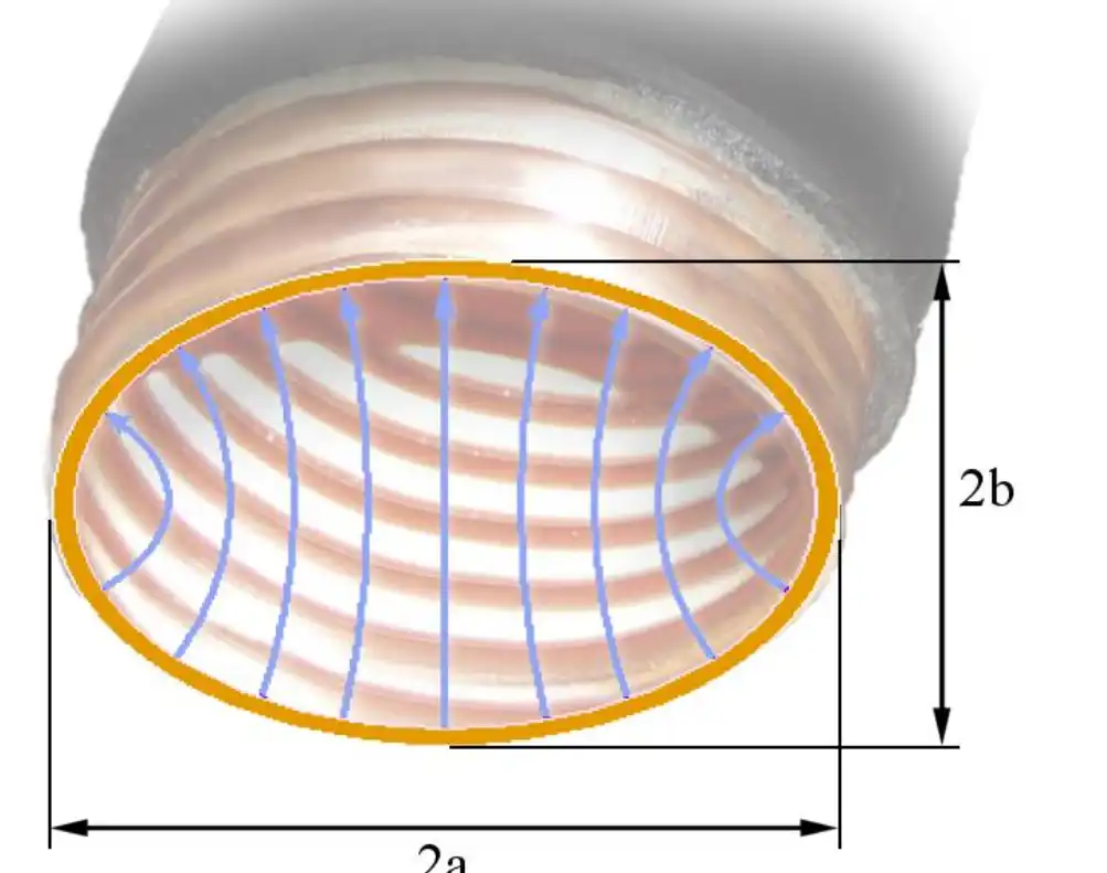
The oval cross-section is better than the spherical one in certain ways. This shape is very good at matching impedances and makes it easy for the main TE₁₁ mode to spread across frequency bands from 3 GHz to 40 GHz. The shape makes it possible to install things in small spaces, like vertical towers and equipment rooms with a lot of people.
When it comes to bands above 2 to 3 GHz, elliptical microwave waveguides are much better than coaxial lines at keeping signals strong. Large-diameter coaxial cables lose their usefulness at these frequencies because of dielectric losses and the conductor skin effect. However, waveguide transmission keeps its low insertion loss even over long distances. Our goods usually have VSWR values below 1.15:1 across the working band, which means that signals are reflected as little as possible and power is transferred as much as possible.
Core Applications Driving Adoption
By far, the most common use for elliptical microwave waveguides is in telecom equipment. Base transceiver stations use these parts to link RF equipment on the ground to antennas on towers, which are usually more than 50 meters up in the air. Being able to make continuous runs without any intermediate flanges makes installation easier and gets rid of any places where signals might get reflected.
These elliptical microwave waveguides are used by satellite earth stations to connect high-power amplifiers to dish feeds. When sending kilowatt-level signals, the ability to handle a lot of power keeps arcing and thermal failure from happening. Corrugated designs are good for defense uses like tactical radar systems because they are mechanically strong and can handle heat expansion and shaking without affecting electrical performance.
The Science Behind Bend Radius in Elliptical Microwave Waveguides
To understand what the bend radius needs to be, you must first understand how electromagnetic waves move through an oval shape. The TE₁₁ mode, which is the main one in these elliptical microwave waveguides, keeps certain field patterns that can't be changed when they are bent. If they are changed, energy is lost.
Electromagnetic Behavior During Bending
The electromagnetic field spread changes in an uneven way when a waveguide turns. Path lengths get longer on the outside of the bend while they get shorter on the inside. This causes changes in impedance that can bounce or spread energy. When bending happens along the E-plane or the H-plane in circular shapes, these effects show up in different ways.
When you bend in the E-plane along the minor axis, the electric field lines up well with the bend geometry, which lets you make radius curves that are closer together. Because the magnetic field components are oriented in a way that makes them more likely to bend, H-plane bending (along the major axis) needs bigger minimum radii. When these minimum requirements aren't met, insertion loss goes up by measurable amounts, usually from baseline values of 0.05 to 0.15 dB per meter to 0.5 dB or more at the bend point.
Material and Frequency Dependencies
The pitch and depth of the corrugations directly affect the bend radius that can be used. Finer corrugations make the structure more flexible, but they may also make it less able to handle power. These trade-offs are taken into account in our engineering standards, which find a balance between mechanical freedom and electromagnetic performance across the frequency range that is needed.
The bending tolerance is also affected by the operating frequency. Higher frequencies have shorter wavelengths, which makes them more sensitive to changes in shape caused by tight turns. Even if the actual measurements stay the same, a waveguide designed for 6 GHz needs less bend radius compliance than one designed for 38 GHz. Because of this frequency-dependent behavior, manufacturers' datasheets need to be carefully read when planning installations.
Comparison with Circular Waveguides
Circular bendable waveguides bend the same way in all directions, which makes planning the placement easier. For elliptical microwave waveguides, however, you need to be aware of the direction of the bend plane. Better electrical performance and better use of the installation room more than make up for this extra complexity. Procurement engineers have to compare these factors with the limitations of the project, such as the tools that can be used and the available routing lines.
Bend Radius Rules: Best Practices for Installing Elliptical Microwave Waveguides
Following the manufacturer's minimum bend radius values to the letter is essential for a successful installation. These specs aren't just ideas; they're important limits that come from modeling electromagnetic fields and analyzing mechanical stress.
Industry-Standard Minimum Values
The minimum bend radius for an E-plane is 150mm to 300mm, depending on the frequency band and elliptical microwave waveguide size. H-plane minimum radii are usually 50–100% bigger than E-plane values. Because magnetic field components are more vulnerable to main axis bending. Advanced Microwave Technologies provides detailed specification documents for each product version that reveal E- and H-plane restrictions.
Even briefly exceeding these minimums during installation might irreversibly distort the curved structure. The accordion-like convolutions may break or twist, creating standing waves and hot patches when the power is strong. Initially undetected, this damage will cause significant VSWR and early failure.
Step-by-Step Installation Techniques
Proper placement starts with route planning. Make a full-scale layout sketch of the bends, orientations, and radii before cutting the elliptical microwave waveguides. This preparation prevents costly and wasteful errors.
The correct bending tools or mandrels will hold the corrugation in place while you bend it. Even though elliptical microwave waveguides may bend, never push them into tighter radii. Support the waveguide sometimes using non-electrical hangers or frames that don't damage the jacket or corrugation.
Installing requires consideration of temperature. Avoid bending in extreme cold. Let the elliptical microwave waveguides adjust to room temperature before working on them. After installation, verify bend radii using radius gauges or templates to ensure compliance. Finally, pressurise and test the system.
Common Installation Pitfalls
Many repeated blunders slow down the system. Installation stress accelerates jacket failure and corrugation fatigue when elliptical microwave waveguides are bent and twisted. Be cautious of your orientation and only employ helical installation pathways if they're built to.
Elliptical microwave waveguides may droop under their own weight if the support spacing is wrong, causing bends that don't match the minimum radius requirements. Support gaps shouldn't exceed the maker's guidelines. This range is generally 1–2 meters, depending on waveguide size and orientation.
After the field is switched off, conductive particles might produce high-power arcing if the metal fragments and other trash aren't cleaned up. Use proper flare tools and thoroughly clean the interior before joining. End quality affects VSWR performance and stability.
Choosing and Procuring Elliptical Microwave Waveguides for Complex Installations
To choose the right elliptical microwave waveguides, you need to carefully look at their electrical specs, mechanical qualities, and the supplier's abilities. When making a purchase decision, it's not just about the unit price; it's also about the total cost of ownership, which includes installation labor, maintenance needs, and the system's useful life.
Interpreting Technical Datasheets
Working frequency range, cutoff frequency, attenuation per unit length, and peak power level are significant characteristics. The frequency range you were provided should cover your broadcast band and some additional room. To eliminate modal dispersion and send just one mode, the cutoff frequency should be significantly lower than the lowest working frequency.
Attenuation standards are usually in decibels per 100 meters. To ensure signal budgets are close with ample tolerance for error, calculate the whole system loss, including turns, junctions, and straight runs. At least twice the maximum transmission power should be used to prevent thermal stress and arcing.
Major and minor axis diameters, corrugation pitch, and jacket thickness affect installation flexibility and environmental performance. Our goods contain accurate corrugations that maintain size over manufacturing runs. This allows items to bend readily and function with all connections.
Balancing Cost and Quality
Poor materials or lax production standards may make cheaper choices less effective. Copper purity impacts electrical conductivity and corrosion resistance. The formulas determine the jacket's temperature range and UV stability. High-purity copper and luxury polyethylene are RoHS-compliant and last for decades.
VSWR homogeneity and connector fit depend on manufacturing precision. Impedance mismatches might degrade system performance if the elliptical axis changes shape or size. Advanced Microwave Technologies is ISO 9001:2008-certified, thus they regulate quality throughout manufacturing. Each waveguide undergoes VSWR sweeping and measurement confirmation before shipping.
Supplier Capabilities and Support
Custom lengths, connections, or jacket requirements are required for complex configurations. Our OEM services include unique elliptical microwave waveguide design, matching flanges and couplers, and field termination kits. Our experts assist with installation and troubleshooting throughout a project.
Global logistics ensures on-time delivery worldwide. We carry basic configurations to complete orders promptly and can handle special requests with reasonable wait periods. After-sales assistance includes measurements, connection recommendations, and warranty servicing for product manufacturing issues.
Troubleshooting and Maintaining Elliptical Microwave Waveguides Post-Installation
Even if they are placed correctly, elliptical microwave waveguides need regular upkeep to keep working well for long periods of time. Environmental factors, mechanical stress, and changes to the system can all cause problems that show up as poor signal quality or no communication at all.
Identifying Bend-Related Problems
High VSWR numbers usually mean that there are impedance discontinuities because of too much twisting or damage to the machine. To find the frequencies where reflections are strongest, use a vector network analyzer to do swept frequency measurements. To find trouble areas, connect these frequencies to real spots along the waveguide run.
It's possible that the mode or circuit is getting worse if the insertion loss goes above and beyond what's specified in the datasheet. Time-domain reflectometry can find specific faults without taking the system apart. You can find trends in gradual decline before they cause system breakdowns by comparing current readings to baselines from when the system was first put in service.
Visual inspection is still a good way to find damaged jackets, weak connectors, or deformations that are easy to see. Look for places where the corrugations look like they have collapsed, sections that are flattened, or kinks. Most of the time, these visible signs are caused by electrical problems that need to be fixed right away.
Preventive Maintenance Routines
Regular check times should be set based on how exposed the system is to the surroundings and how important it is. Temperature- and UV-ray-sensitive tower-mounted installations need to be checked more often than climate-controlled indoor runs. We suggest full inspections once a year, which should include a visual check, checking the torque on the connectors, and electrical testing.
For pressurized systems, dry air or nitrogen pressure needs to be monitored to find jacket holes that let water in. Keeping the internal pressure high stops moisture, which leads to rust and dielectric breakdown. Pressure tracking systems that send out alarms let you know right away if a seal fails.
As part of regular upkeep, connectors need to be cleaned and re-torqued to keep the contact pressure steady. Over time, thermal cycling and vibration can loosen connections, causing them to make intermittent contact that leads to intermodulation products and hot spots. To keep threads from getting damaged by over-tightening, use regulated tools and follow the manufacturer's torque specs.
Repair and Replacement Decisions
If the perforated conductor stays whole, minor damage to the jacket may be able to be fixed with approved fixing materials and methods. Copper that is exposed to air needs to be fixed right away to keep it from oxidizing. Compare the cost of repair to the cost of replacement, taking into account the time and work needed to fix the system.
Sections that are kinked or badly deformed can't be fixed consistently and need to be replaced. Trying to straighten out collapsed corrugations doesn't usually bring back the original electrical performance and may even cause more stress to build up. When it's time to change something, write down the failure mode and root cause so that it doesn't happen again in future installs.
Conclusion
The most important thing for installing elliptical microwave waveguides correctly and making sure they work well in the long term is making sure the bend radius compliance is correct. When planning routes, installing things, and doing regular repairs, it's important to pay close attention to the different ways that E-plane and H-plane bends. To make sure the whole system works, procurement choices must strike a balance between electrical performance requirements, mechanical qualities, and the supplier's abilities.
We at Advanced Microwave Technologies Co., Ltd have been making elliptical microwave waveguides for 20 years and are committed to ISO 9001:2008 standards. This means that the waveguides we sell will meet the strict needs of defense systems, satellite communications, and internet infrastructure. By knowing and following the right bend radius rules, you can protect your investment and get the best signal quality over the life of the system.
FAQ
What is the minimum bend radius for elliptical waveguides?
The smallest bend radius depends on the size of the elliptical microwave waveguides and the direction of the curving plane. For E-plane bending, radii are usually between 150 and 300 mm, but for H-plane bending, they need to be 50 to 100 % bigger. Always check the manufacturer's specs for the product you have because these numbers depend on the frequency band and corrugation shape. When basic requirements aren't met, signals and shapes become permanently deformed.
How does improper bending affect signal transmission?
When you move something too much, it changes the modes and creates impedance gaps that make insertion loss and VSWR worse. When the electromagnetic field pattern is messed up, energy is reflected, and the potential mode changes to a higher-order mode. In systems with more than one carrier, these effects show up as weaker signals, higher noise levels, and possible intermodulation distortion.
Can elliptical waveguides be customized for tight installation spaces?
Advanced Microwave Technologies offers customization services that may include better corrugation patterns and special materials that may allow for tighter twisting within the limits of electromagnetic fields. Talk to our tech team about your unique routing problems to find workable answers. Custom elliptical microwave waveguides find the right balance between being mechanically flexible and meeting the electrical performance needs of your specific application.
Partner with a Trusted Elliptical Microwave Waveguide Supplier
For mission-critical uses, Advanced Microwave Technologies Co., Ltd makes elliptical microwave waveguides that are precisely designed to provide excellent electrical performance and mounting freedom. Our corrugated copper structure and UV-resistant jacketing give your defense, telecommunications, and satellite systems the stability they need. Plus, our ISO 9001:2008 certification makes sure that the quality is the same in every production run.
In addition to making high-quality products, we also offer full technical help, such as fitting advice, advice on bend radius, and OEM solutions that are custom-made to fit the needs of your project. Our engineering team has over 20 years of experience in the field and can help your project succeed, whether you need standard configurations delivered quickly or custom designs to solve difficult routing problems.
Get in touch with craig@admicrowave.com right away to talk to our technology experts about your elliptical microwave waveguide needs. We offer low prices for large orders, fast shipping around the world, and help after the sale that keeps your systems running for decades.
References
1. Marcuvitz, Nathan. "Waveguide Handbook: Elliptical Waveguides and Their Propagation Characteristics." Boston Technical Publishers, 1986.
2. Ramo, Simon, John R. Whinnery, and Theodore Van Duzer. "Fields and Waves in Communication Electronics: Bend Radius Effects on Mode Purity." John Wiley & Sons, 1994.
3. IEEE Standard 1785-2016. "IEEE Standard for Rectangular Metallic Waveguides and Their Interfaces for Frequencies of 110 GHz and Below: Installation Practices."
4. Collin, Robert E. "Foundations for Microwave Engineering: Flexible Waveguide Transmission Systems." IEEE Press, 2001.
5. ITU-R Recommendation SM.329-12. "Unwanted Emissions in the Spurious Domain: Effects of Installation Practices on Waveguide Systems."
6. Montgomery, Carol G., Robert H. Dicke, and Edward M. Purcell. "Principles of Microwave Circuits: Mechanical Design Considerations for Flexible Waveguides." IET Publications, 1987.
YOU MAY LIKE
 VIEW MORELow Ku Band Diplexer
 VIEW MORERF Power Detector
 VIEW MOREWaveguide Straights and Transitions
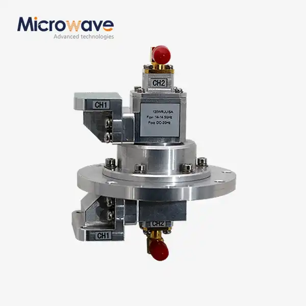 VIEW MOREWG Dual-Channel Rotary Joint
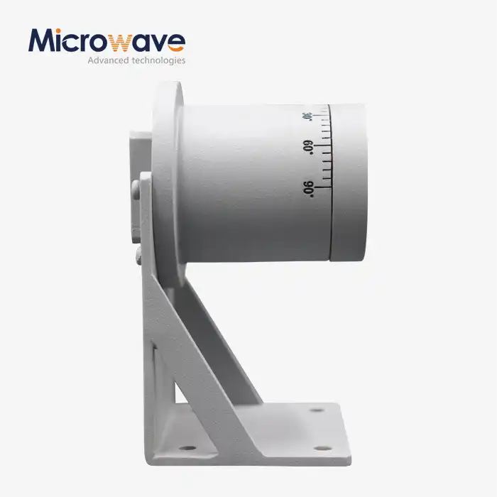 VIEW MORE90° Polarized Rotary Joint
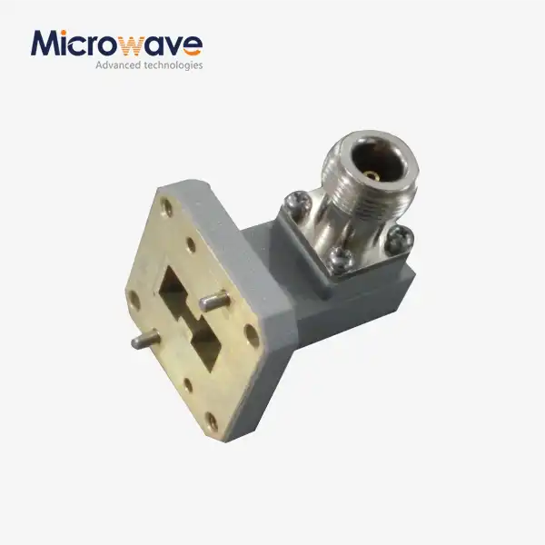 VIEW MOREDouble Ridged WG To Coaxial Adapter
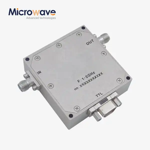 VIEW MOREDigitally Controlled Phase Shifter
 VIEW MORECorrugated Horn and Multimode Horn Antenna
