Are Low Insertion Loss Isolators Essential for Reliable Networks?
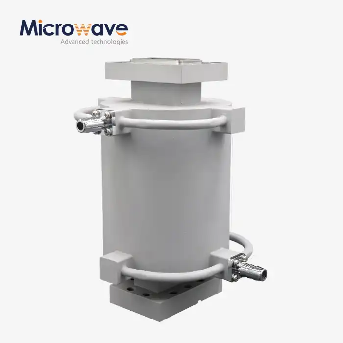
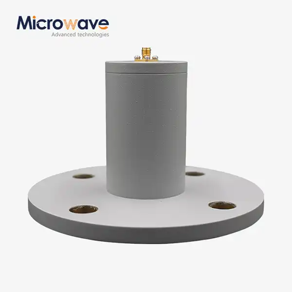
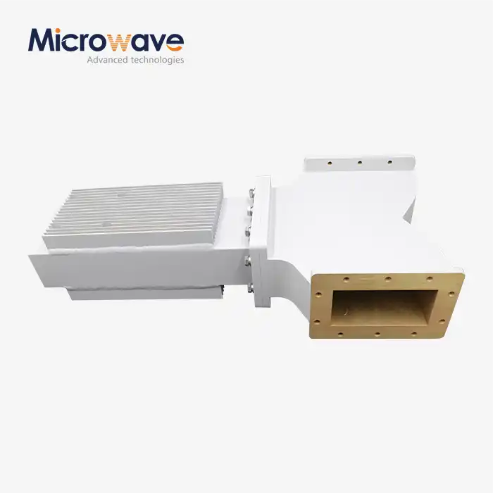
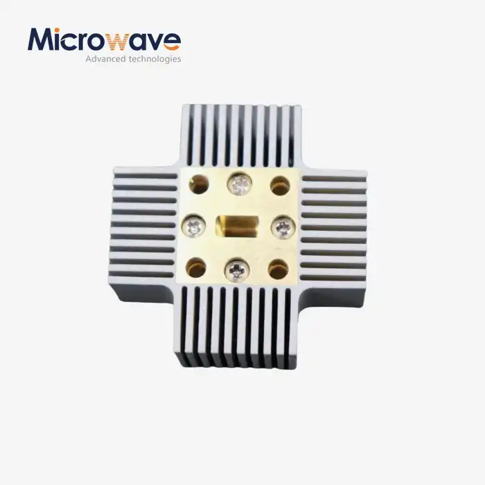
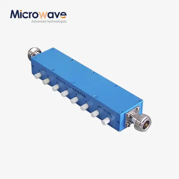
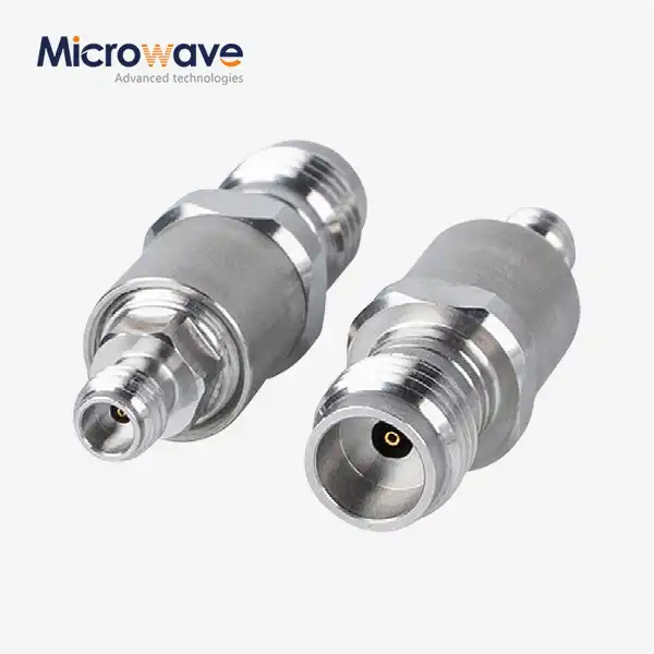
Low insertion loss isolators are indeed essential for reliable networks, particularly in mission-critical applications where signal integrity cannot be compromised. These specialized passive components permit forward signal transmission with minimal attenuation—typically under 0.5 dB—while blocking reflected energy that could destabilize transmitters or degrade system performance. In environments such as satellite ground stations, defense radar arrays, and telecommunications infrastructure, even fractional decibel losses accumulate across the signal chain, reducing effective radiated power and reception sensitivity. By minimizing energy dissipation and protecting vulnerable amplifier stages from reverse power, these devices serve as crucial safeguards that enhance uptime, extend component lifespan, and ensure consistent throughput under demanding operational conditions.
Understanding Low Insertion Loss Isolators: Definition and Working Principles
Low insertion-loss isolators are a special type of ferrite-based passive device that lets signals flow in only one direction with little energy loss. At their heart, these parts use the Faraday rotation effect in magnetically biased ferrite materials. This lets electromagnetic energy move easily in one direction while blocking signals that are traveling the other way by 20 dB or more. Low insertion loss is what makes this technology unique. It is made possible by carefully choosing high-Q ferrite compositions, designing magnetic circuits in the best way possible, and carefully milling to eliminate gaps at joint surfaces.
Technical Specifications and Frequency Coverage
Modern isolators work with a wide range of frequency bands, from L-band (1–2 GHz), which is used for GPS and mobile communications, to C-band and X-band for satellite uplinks, and finally Ka-band (26.5–40 GHz), which supports next-generation internet services. Insertion loss specs change based on frequency. C-band units usually get 0.2–0.4 dB, while millimeter-wave models might get 0.6–0.8 dB because of higher frequency-related material losses. Return loss, which measures how well the device matches resistance, usually goes over 20 dB to stop standing waves that damage signal integrity.
Benefits Across High-Reliability Sectors
Putting these parts together has benefits that go far beyond simple loss metrics. In phone networks, lowering insertion loss directly leads to more link budget margin, which lets operators increase coverage or lower transmit power, which lowers operational costs. Less signal energy is turned into heat, which lowers the thermal loads in data centers and makes cooling more efficient in computer racks that are close together. Lightweight waveguide isolators that are both mechanically tough and electrically efficient are used in aerospace systems, where every watt of power and gram of weight counts. High-power isolators are used in defense radar systems to keep sensitive receiver front-ends safe from high-energy pulses. This keeps the receivers from becoming less sensitive, which could make it harder to spot threats.
Working with satellite service providers has shown us that choosing the right isolators can lower the overall system noise temperature by 0.3 to 0.5 dB. This is a big difference when link margins are tight because of rain fade or long slant ranges.
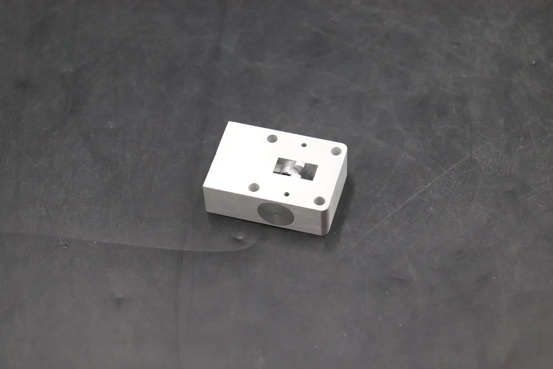
Low Insertion Loss Isolators vs. Other Isolator Types: A Comparative Analysis
To know when to choose a low insertion loss isolators over other passive components, you need to know the performance trade-offs and the specifics of the application. Isolators all work to keep upstream parts safe from reflected power, but they are very different in how they work electrically and physically.
Comparing Key Device Categories
Standard isolators put isolation performance—often more than 25 dB—above insertion loss, which can reach 0.8 to 1.2 dB. This trade-off works well in situations where reflected power is very dangerous, like when guarding solid-state power generators in pulsed radar systems. Devices that are designed for low insertion loss, on the other hand, give up some separation cushion (18–22 dB) to keep forward signal attenuation to a minimum. This balance works great for receiver chains and continuous-wave systems where sensitivity is affected by loss that builds up over time.
Circulators are similar to isolators in that they route signals between three or more ports with similar loss properties. They also allow for more complex signal routing. In transceiver systems, a three-port circulator can split the send and receive lines, so it can work as both an isolator and a diplexer. However, the fact that they have multiple ports adds to their complexity and cost, but this makes them good when two-way isolation is needed instead of just one-way protection.
Even though high insertion-loss isolators aren't used as much in new designs, they are still useful in older systems or when cost is more important than performance. In modern high-performance networks, where every tenth of a decibel counts toward system efficiency, their higher loss—which can be more than 1.5 dB—is usually not acceptable.
Performance Impacts and Selection Scenarios
VSWR, or Voltage Standing Wave Ratio, is another important factor. VSWR should stay below 1.25:1 in a well-designed isolator so that there aren't many echoes at the device ports. When procurement teams compare different models, they should ask for full S-parameter data across the working span to make sure that the models perform consistently. Temperature stability is also very important: military-grade units must meet specifications from -55°C to +85°C, while most commercial telecom equipment works between 0°C and +50°C.
The price changes seen in 2024 are due to the cost of materials and the difficulty of making the goods. Prices for commercial C-band coaxial isolators vary from $150 to $400 per unit, based on the power level and packaging. For Ka-band satellite terminals, custom waveguide models can cost more than $1,200. Costs can be cut by 15–25% through bulk purchases and long-term supply deals. This makes ties with suppliers an important strategic issue.
Selecting the Right Low Insertion Loss Isolator for Your Network
Aligning technical specs with application needs is very important when making procurement decisions, along with checking out a supplier's skills to make sure they can perform and provide help throughout the lifecycle. We suggest a structured evaluation framework that takes into account both criteria for performance and practical issues.
Frequency Compatibility and Power Handling
It is very important that the operating band of the low insertion-loss isolator matches the frequency plan of your system. When there is a mismatch, there are out-of-band losses or poor isolation at critical frequencies. Peak and average power levels must be taken into account when figuring out power handling capacity. For example, a satellite uplink that sends 50 W of continuous wave needs a device rated for at least 75 W to allow for thermal margin. For pulsed applications, it's important to pay attention to the peak power requirements because ferrite overload at high rapid fields can damage or temporarily lower performance.
Evaluating Supplier Credentials and Documentation
When it comes to consistency and after-sales help, a brand's image stands in for both. Companies that have been around for a while, have ISO 9001 certification, and have quality systems that can be tracked show that they are committed to process control. Our 24m Microwave Darkroom at Advanced Microwave Technologies Co., Ltd (ADM) lets us fully characterize everything from 0.5 to 110 GHz, making sure that every isolator meets the published specs before it is shipped. Datasheets must be clear: they must include specific electrical parameters, mechanical sketches with tolerance callouts, and environmental ratings. This way, integration teams can make smart choices without having to go through expensive prototyping rounds.
When it comes to custom uses, OEM relationships are especially useful. Our engineering team works with defense contractors to make ruggedized waveguide isolators that meet MIL-DTL-85 environmental standards for shock resistance, hermetic sealing, and mounting. These kinds of agreements also make design-for-manufacturability reviews easier, which cuts down on lead times and unit prices for large production runs.
Logistical Considerations for Enterprise Procurement
When planning system builds, lead time planning is very important. Catalog items usually ship in two to four weeks, but unique designs need eight to twelve weeks for tooling and approval. Buying in bulk not only lowers the cost per unit, but it also makes sure that inventory is distributed evenly during times when the supply chain is tight. We keep strategic stocks of parts to help customers who need things quickly, like satellite operators who need emergency replacements for spare programs in space.
Custom orders let you improve performance in ways that you can't do with off-the-shelf products. You can get the most out of your system and make integration easier by choosing non-standard frequency splits, interface flange types, or power rates that are specific to your operating envelope.
Optimizing Network Reliability with Low Insertion Loss Isolators
By strategically placing these low insertion loss isolators, you can fix common failure modes and performance problems that happen in complicated RF systems. Field experience in the defense, telecom, and aerospace sectors shows similar patterns of execution that get the best return on investment.
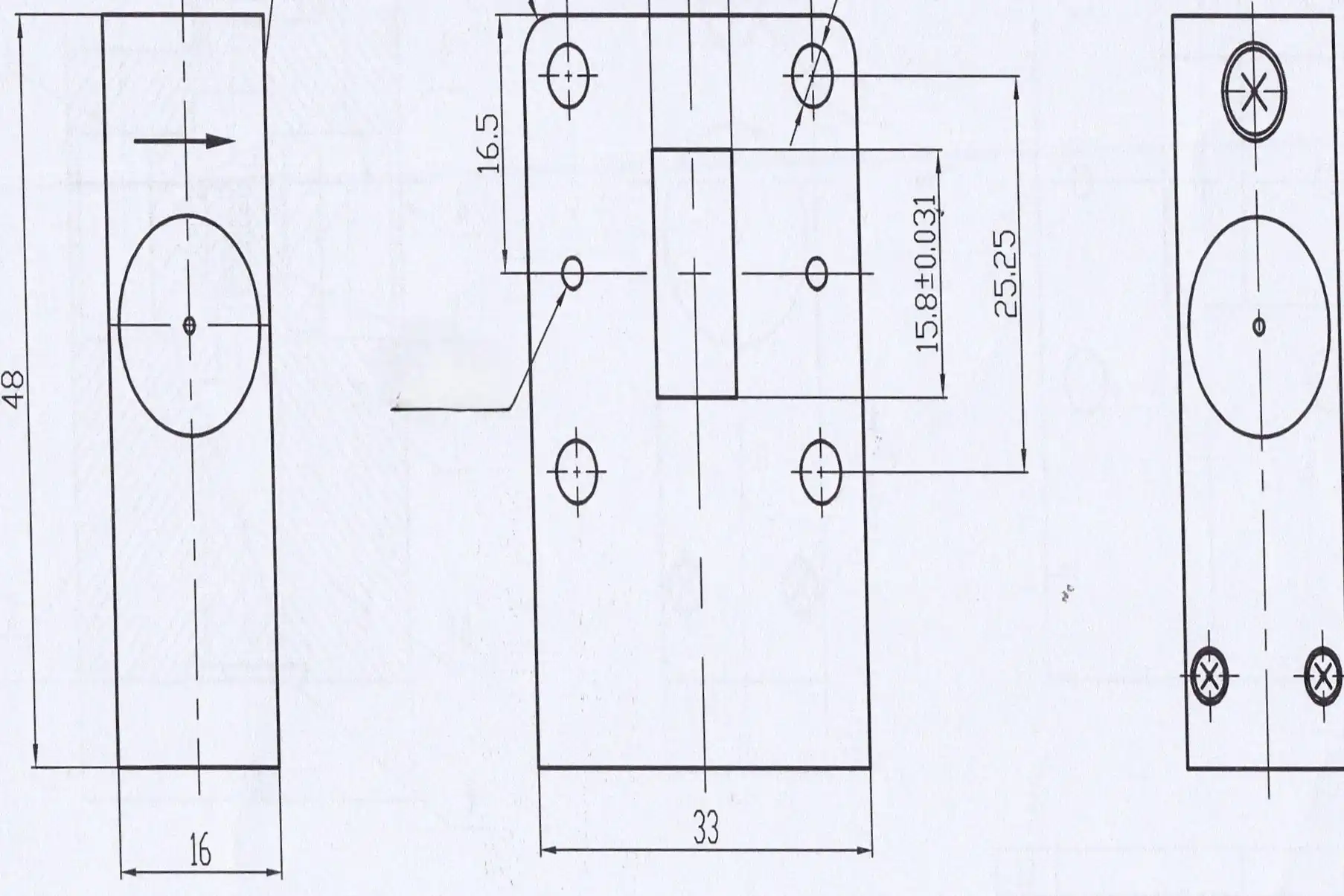
Installation Best Practices
When mechanical integration is done right, performance doesn't drop because of stress-induced ferrite breaking or magnetic circuit mismatch. To keep the electrical connection without warping the housing, waveguide isolators need careful pressure control on the flange bolts, which is usually 10–15 in-lbs for WR-90 flanges. For coaxial types, installing them directly with as little bending as possible on the wires next to each other helps keep the impedance matching. Paying attention to thermal management is also important. Putting isolators on heat-dissipating chassis or adding forced-air cooling can make high-power applications last longer.
Maintenance Strategies for Longevity
Performance degradation is caught by scheduled checks before it affects the availability of the system. Every year, a calibrated vector network analyzer is used for swept-frequency testing to make sure that insertion loss and isolation stay within acceptable limits. Corrosion or physical damage that could cause intermittent problems can be seen by looking at the connection ports. Protective coatings and environmental sealing can increase the average time between failures from five to over ten years in maritime or coastal installations where salt fog speeds up oxidation.
Case Study: Satellite Ground Station Upgrade
A area phone company came to us because their Ku-band transfer link was constantly unstable. An investigation showed that older circulators had 1.8 dB insertion loss, which was much higher than the 0.4 dB that was supposed to be there. This was because the magnets stopped being magnetic and the ferrites aged. When we replaced these with our low insertion-loss isolators, 1.4 dB of link margin was recovered. This stopped weather-related outages during mild rain events. Based on the saved downtime and lower send power consumption, the operator figured the payback period would be less than 18 months.
Emerging Technologies and Future Outlook
Researchers working on temperature-compensated ferrite formulations hope to make isolators that work the same way across a wider range of temperatures. This is very important for space uses that have to withstand extreme cycles. With additive manufacturing, complex internal shapes can be made that improve the consistency of the magnetic field and could cut insertion loss by an additional 0.1 to 0.2 dB. As 5G millimeter-wave networks spread and satellite systems grow into V-band (40–75 GHz), the need for ultra-low-loss isolators will grow. This will lead to more advances in materials science and precision manufacturing.
Conclusion
Low insertion loss isolators are essential parts of current high-reliability networks because they protect the purity of signals and keep energy use to a minimum. With almost no forward loss, they protect sensitive receiver stages and power amplifiers from damaging reflections, which directly improves link costs and system uptime. When choosing the right device, you need to pay close attention to frequency compatibility, power ratings, and supplier qualifications—factors that separate robust, long-lived installations from those plagued by premature failures. As 5G is deployed and satellite constellations grow, network demands will rise. These passive guards will continue to be important parts of the communication infrastructure that makes global access possible.
FAQ: Key Questions About Low Insertion Loss Isolators
What frequency ranges do these isolators support, and how does performance vary?
From less than 1 GHz to more than 100 GHz, you can find low insertion-loss isolators, and each one works best in a certain band. Lower frequencies (L-band to X-band) usually have insertion losses of less than 0.3 dB and separation of more than 22 dB. Millimeter-wave versions (Ka-band and above) have a little more loss—0.6 to 0.8 dB—because the ferrite material loses more at higher frequencies. Always make sure that the isolator's stated bandwidth covers your whole operational range, including any guard bands.
When should I choose a low insertion loss isolator over a high isolation model?
This choice depends on which parameter has the biggest effect on your system. Even if separation is only 20 dB instead of 25 dB, receiver front-ends and low-noise amplifier stages work better when insertion loss is kept to a minimum. On the other hand, in high-power systems, transmitter security focuses on maximum separation to keep amplifiers from being damaged by antenna mismatches, even if it means a little higher loss. Look at your link budget analysis to figure out how much each decibel saved or gained is worth.
Can suppliers provide customized isolators for unique applications?
Reputable manufacturers regularly create custom solutions to meet unique user needs. Through joint engineering, you can get custom center frequencies, unique flange connections, wider temperature ranges, and high-power versions. ADM's OEM services include fast prototyping, design proof in our 110 GHz labs, and full production that is in line with ISO 9001 and RoHS. Giving detailed specifications and information about the application early on in the process makes sure that the designs meet your exact needs without having to go through expensive redesign cycles.
Partner with ADM for High-Performance Isolator Solutions
To get the best network performance, you should start by picking a low insertion loss isolators supplier that offers both excellent technical support and quick response times. ADM brings more than 20 years of experience in microwave engineering to every project, backed by state-of-the-art measurement tools and strict quality systems that are certified to ISO 9001:2015 standards. Our engineering team is ready to help you make a choice, whether you need regular catalog items or ideas that are completely unique and meet your exact needs.
To speed up integration, we offer complete datasheets, S-parameter files, and mechanical models. When you buy in bulk, you can get good deals on large amounts of product, and our OEM services can get you samples in weeks instead of months.
ADM has a history of success in the satellite communications, aerospace, and defense industries that can help you make your system more reliable and efficient. Email craig@admicrowave.com right now to talk to our experts about your needs.
References
1. Pozar, David M. Microwave Engineering, 4th Edition. Hoboken: John Wiley & Sons, 2011.
2. Helszajn, Joseph. Ferrite Phase Shifters and Control Devices. New York: McGraw-Hill, 1989.
3. Carter, R. G. "Electromagnetic Theory and Applications in Beam-Wave Electronics." IEEE Transactions on Microwave Theory and Techniques, vol. 52, no. 3, 2004, pp. 850–865.
4. "Waveguide and Coaxial Isolator Design for Satellite Communication Systems." International Journal of RF and Microwave Computer-Aided Engineering, vol. 28, no. 6, 2018, pp. e21245.
5. Kumar, Anil and Singh, Rajesh. "Performance Analysis of Ferrite Isolators in High-Power Microwave Systems." Journal of Electromagnetic Waves and Applications, vol. 33, no. 12, 2019, pp. 1545–1560.
6. MIL-DTL-85, Detail Specification: Isolators and Circulators, Radio Frequency, General Specification For. United States Department of Defense, 2015.