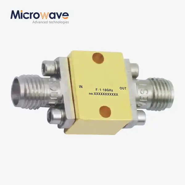
How to Spot Directivity Errors After Directional Coupler Calibration
It's necessary to check key performance factors in a planned way after directional coupler calibration in order to find mistakes in the direction of the signal. First, use a calibrated vector network analyzer to check the separation between the linked and isolated ports. Then, compare the results to the manufacturer's instructions. Directivity mistakes usually show up as bad isolation readings, strange changes in coupling across frequency ranges, or return loss patterns that aren't symmetrical. Environmental factors, such as changes in temperature or worn-out connectors, can cause measurement drift during directional coupler calibration. This is why post-calibration testing is so important for mission-critical applications that need accurate measurements.
Understanding Directivity Errors in Directional Couplers
The ability of a directional coupler to tell the difference between forward and mirrored power signals moving through a transmission line is called its directivity. When directivity drops, the device can't clearly tell these signals apart. This leads to measurement uncertainty that spreads through your whole RF system. We've seen this problem happen over and over again in places like satellite ground stations and military radar sites where accuracy is very important.
What Causes Directivity to Degrade After Calibration
Even after strict testing processes, directivity is lost because of a number of factors working together. Connector mating surfaces pick up tiny particles that change how impedance matching works, and material growth during operation is caused by temperature cycling, which changes how electromagnetic coupling works. Calibration methods can sometimes cause mistakes by not defining the reference plane correctly or not sampling frequencies densely enough across the working band.
The Business Cost of Overlooked Directivity Problems
A lot of the time, procurement managers don't think about what mistakes in directivity will mean for the rest of their supply lines. According to data from the industry, when aerospace companies put couplers into radar systems that don't have enough directivity, the measurement uncertainty causes designers to be more careful, which drives up the cost of parts by 15 to 30 percent. When ground station technology can't correctly measure reflected power, it causes antennas to not match up properly and links to become less available during severe weather events, which are similar problems that satellite communication companies face.
How Directivity Relates to Other Performance Parameters
In a coupler's specification sheet, directivity is not listed separately. It changes over time with insertion loss, coupling factor, and frequency flatness to determine the accuracy of the whole measurement system. Even if a coupler has great directivity but a bad frequency response, readings across broad applications will still not be accurate. We've seen buying teams choose couplers based only on their directivity specs, without thinking about how the temperature coefficient affects the stability of outdoor setups over time.
Step-by-Step Guide to Spot Directivity Errors After Calibration
To find directivity mistakes in directional coupler calibration, you need thorough checking methods that go beyond simple pass/fail tests. Your method should strike a balance between being thorough and running out of time, especially when you're looking for suppliers for large-scale production projects.
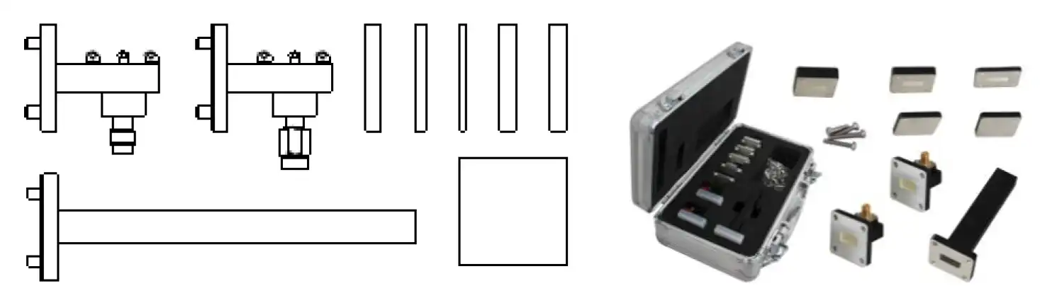
Set clear goals for the beginning before you start measuring. Check the calibration certificates to make sure they can be traced back to national standards like NIST. Also, make sure the frequency of the calibration matches the needs of your application, and make sure the conditions during the original calibration were the same as the ones you'll be using it in.
Review Calibration Documentation and Compliance
Check marks can tell you something if you know what to look for. We always look at the real measurement error budgets instead of just the main details. Does the license say whether the signal is directed at single spot frequencies or across continuous bands? Are the types of connectors and torque requirements written down? These details show if the tuning process was tailored to your unique needs or if it used general steps that weren't good enough for precise tasks.
Measurement Techniques Using Specialized Instruments
For accurate directivity verification, the right test tools must be set up properly. Vector network analyzers are still the best way to fully characterize a coupler because they can measure all S-parameters at the same time across frequency. Using precision phase-matched wires, connect the analyzer to the coupler's mainline ports. Then, measure the isolation between the coupled and isolated ports as you move across your working band. Keep an eye out for waves or nulls that don't make sense. These can be signs of problems with the connectors or the internal connection path.
Power meters and precise signal generators can be used instead of VNAs when they are not accessible. This method checks the output of the coupled port at known incident power levels. It then changes the way of the signal to find out how much unwanted coupling is happening from the separated port. The ratio of these measures shows good directivity, but it needs more work from a person than automatic VNA sweeps.
Environmental Considerations and Maintenance Scheduling
Temperature has a big effect on coupler directivity because it causes internal structures to expand and dielectric constants to shift in base materials. We suggest that you check the directivity at weather extremes that are similar to those in your work setting, not just in a lab where the conditions are comfortable. Humidity also lowers performance in designs that aren't protected because dielectric materials soak up water, which is especially bad for couplers that work above 18 GHz.
The length of time between maintenance tasks should depend on how important your application is and how it will be used. Defense radar systems need to be checked once a year, while satellite ground stations in difficult environments may need to be checked every six months. In controlled industrial study settings, intervals can often be pushed back to 18 to 24 months without affecting reliability.
Common Directivity Error Patterns and How to Diagnose Them
Identifying common error signs speeds up fixing and lowers the cost of diagnostics. When different types of failure happen, they leave behind different measurement trends that point to different root causes.
Frequency-Dependent Directivity Degradation
If the directivity goes down gradually toward the band ends but stays fine at the center frequencies, it could mean that the calibration frequency sampling isn't good enough or that there are resonant effects in the internal coupling structures. We found this trend in couplers that were made by companies that optimized them for narrow frequency uses but sold them for wideband use. To find problems, compare measured directivity curves with specs drawn at the same frequency precision from the datasheet.
Sudden Directivity Drops at Specific Frequencies
Sharp directivity nulls at frequencies that are not connected to anything else in directional coupler calibration usually mean that there are connection resonances or standing wave patterns caused by impedance gaps. Disconnect and restore all RF connections with the right amount of force, then measure again to see if the null frequencies change. If they do, it means the problem is with the connectors and not the couplers themselves. Write down torque values using measured tools because too much torque deforms connection dielectrics, and too little torque creates air gaps that change impedance in a big way.
Asymmetric Directional Performance
When measuring forward and mirrored power flow, couplers should have the same amount of directivity. If the imbalance is big, it means that there is damage inside the device, like bond wires that are lifted or substrates that are cracked, that affects one binding line more than the other. This pattern often shows up in couplers that are shipped with mechanical shocks. This is something that procurement teams should look into by including packing standards in contracts with suppliers.
Making a good diagnostic process gives structure to fixing that might otherwise be done randomly. We suggest starting with a close-up eye review of the connector, then moving on to electrical testing at room temperature, and finally, environmental testing if the first results aren't clear. Take pictures and save data files of every measurement so that the company can learn about how source quality has changed over time.
Comparison of Directional Coupler Calibration Methods and Their Impact on Directivity
How the directional coupler calibration is done has a big effect on how accurate the directivity is and how stable it is over time. When procurement teams understand these trade-offs, they can include the right calibration methods in seller deals.
Analog Versus Digital Calibration Approaches
In traditional analogue calibration, actual parts like tuning screws or variable capacitors are changed to get the best directivity across all frequency bands. This method works very well at first, but over time, as the adjustment parts wear out, it starts to move mechanically. Digital calibration uses mathematical correction factors to fix observed data. Lookup tables or algorithms are used to make up for known limits in directivity. Digital methods are better at keeping things stable, but they can't fix mistakes that are bigger than a certain point without adding too much measurement noise.
Hybrid methods that use both techniques have clear benefits. First, physical optimization sets the standard performance for directivity. Next, digital correction improves accuracy across the whole working range. We chose this method for satellite communication systems that need more than 40 dB of directivity over multiple octave bandwidths, which is hard to do with analogue methods alone.
Industry Standards and Best Practices
Leading makers use calibration methods that are in line with military, IEEE, and IEC standards that say how much measurement error is acceptable. Keysight Technologies stresses the importance of full two-port calibration using known standards to set accurate reference planes. This is especially important when describing directivity, since uncertainty in the reference plane affects isolation measures directly. Anritsu recommends calibration settings that are kept at a constant temperature and wire setups that are phase-matched to reduce systematic mistakes. Rohde & Schwarz shows how important it is to test the repeatability of connectors by showing that differences in the connector interface cause more measurement error than differences in the internal coupler features in well-designed parts.
Instead of using vague language like "calibration included," procurement requirements should directly refer to these standards. Need to see calibration records that include environmental variables, measurement error budgets, and tracking chains. This paperwork is very helpful during quality checks and can be used as evidence when problems with direction show up months after the delivery date.
Procurement Insights: Selecting Services and Equipment to Ensure Reliable Directional Coupler Calibration
Strategic choices about buying have to weigh the needs for technical performance against budget limits and the practicalities of the supply chain. Which method to use relies on how important your application is, how much it needs to be used, and your company's expert skills.
Evaluating Calibration Service Providers
The quality of a testing service starts with being accredited. Accreditation by ISO/IEC 17025 shows that service providers have recorded quality systems, qualified staff, and measurement standards that can be tracked. Besides checking the provider's basic accreditation, look at scope certificates to make sure that their accreditation covers the frequency ranges and parameter types that you need. A lab that is approved to measure power might not be approved to characterize directivity, which could leave holes in your quality paperwork when it comes to tracking.
Technical skills are just as important. Does the service company keep environmental rooms for calibrating with changing temperatures? Can they work with your socket types without the need for adapters, which can be confusing? How accurate are their measurements at the frequencies you use? In some cases, the cheapest service sent us calibrations with uncertainty bands that were bigger than the standard tolerances we needed to check. These calibrations were technically correct, but they weren't useful for our needs.
Pre-Calibrated Couplers Versus In-House Calibration
Buying pre-calibrated couplers from reliable sellers of directional coupler calibration makes the buying process easier, but the maker now controls the calibration method. This method works well for normal uses with common connection types and frequency bands. Even though it costs more at first, organizations that need to do specialized calibration processes (for example, because of odd frequency ranges, harsh weather conditions, or custom reference planes) benefit from building their own capabilities.
Based on industry standards, the economic split point usually happens between 50 and 100 couplers per year. Below this number, it makes financial sense to outsource testing. Above this point, spending money on VNA tools and trained staff gives a good return on investment while also speeding up testing and giving you more options.
Maintaining Long-Term Calibration Quality
Directional coupler calibration is not a one-time thing; it's an ongoing process that needs to be managed in a planned way. Set calibration intervals based on what the maker says, with any changes made based on your working experience. Track readings of directivity over time to find patterns of slow drift that show when something is about to break down or needs repair. This moving data is very helpful when negotiating with suppliers because it shows how performance actually compares to what was promised.
Service contracts with testing providers let you plan ahead for costs and get first-choice booking during busy times. Talk about quick return times in contracts so that they can be used in emergencies. This is especially important if a link fails and stops a satellite communication system from working or if an aerospace program milestone is delayed. When compared to the costs of working delays in mission-critical applications, the extra cost for faster service is almost nothing.
At Advanced Microwave Technologies Co., Ltd., we're known for providing high-quality RF and microwave parts that perform above and beyond in even the toughest situations. Our 24-meter Microwave Darkroom lets us test antennas and couplers completely from 0.5 to 110 GHz, giving us verification abilities that are on par with or better than those of big calibration labs. We can send pre-calibrated directional couplers with performance specs that can be tracked back to international standards thanks to this infrastructure.
Conclusion
After testing, mistakes in direction affect the accuracy of measurements in ways that affect whole RF systems, leading to quality problems and running costs that are much higher than the price of the component. Systematic verification processes that include reviewing documents, using the right measurement methods, and being aware of the surroundings make it possible to reliably find these mistakes before they affect the performance of the system. Strategic purchases that take into account testing methods, service provider capabilities, and long-term quality upkeep are what separate programs that work from those that have problems with measurement reliability over and over again. Taking the time to learn about these factors will directly lead to lower system development risk and higher operating efficiency in research, defense, space communications, and aerospace.
FAQ
1. How Often Should Directional Couplers Undergo Calibration?
How often you calibrate relies on how important the application is and how exposed it is to the surroundings. For aerospace and defense systems, calibration is usually needed once a year to keep up with contractual quality standards. On the other hand, business telecommunications equipment is usually serviced every 18 to 24 months. To keep measurement tracking, lab reference standards need to be calibrated once a year. Environmental factors make calibration more necessary. For example, couplings that are installed outside or in places with a lot of shaking may need to be checked every six months.
2. What Equipment Is Essential for Detecting Directivity Errors?
Vector network analyzers measure all four S-parameters at the same time across frequency bands, giving the most complete picture of directivity. As a minimum, the specs should include frequency coverage that works for your application, a dynamic range that is 10-15 dB higher than the expected directivity, and the ability for the calibration kit to work with your socket types. Power meters with precise signal sources can also be used to measure directivity through sequential testing, but this method is less automated, and results are less accurate.
3. Can Calibration Completely Eliminate Directivity Errors?
Calibration can cut down on directivity mistakes, but it can't get rid of them completely. There are real lower limits on how much directivity can be achieved because of issues with coupler design, connection repeatability, and measurement system noise floors. When properly adjusted, high-quality couplers can usually meet directivity requirements of 30 to 45 dB, which is more than enough for most uses. For ultra-precision tasks that need better performance, coupler designs that have better isolation structures and manufacturing limits that go beyond what is possible with normal testing are needed.
Partner With ADM for Precision Directional Coupler Solutions
The Advanced Microwave Technologies Co., Ltd. has been working with microwaves for over 20 years and uses ISO 9001:2008 approved production methods to make directional coupler calibration directional couplers and calibration solutions that meet the strictest standards in aerospace and defense. Our engineering team provides full technical support throughout the whole buying process, from creating the initial specifications to helping you integrate the goods after delivery. Whether you need standard couplers from our catalogue or custom units made for certain frequency bands and environmental conditions, we can help. Our advanced measurement facilities and fast prototyping make it possible for us to make what you need. Get in touch with our applications engineers at craig@admicrowave.com to talk about your directional coupler needs with a reputable maker and provider that knows how important it is for mission-critical applications to have verified directivity performance.
References
1. Dunsmore, J. P. (2012). Handbook of Microwave Component Measurements: with Advanced VNA Techniques. Wiley-IEEE Press.
2. Pozar, D. M. (2011). Microwave Engineering, 4th Edition. John Wiley & Sons, Inc.
3. Institute of Electrical and Electronics Engineers (2017). IEEE Standard for Precision Coaxial Connectors at RF, Microwave, and Millimeter-wave Frequencies. IEEE Std 287-2017.
4. Keysight Technologies (2019). Applying Error Correction to Network Analyzer Measurements. Application Note 1287-3.
5. National Institute of Standards and Technology (2018). Guidelines for Evaluating and Expressing the Uncertainty of NIST Measurement Results. NIST Technical Note 1297.
6. Anritsu Corporation (2020). Understanding Vector Network Analyzer Measurements for Directional Coupler Characterization. Technical Brief 11410-00989.