





Why Broadwall Coupler Dominates in Satellite Test Equipment?
The broadwall coupler is the most trusted choice in the business when satellite test systems need to be very precise and reliable. These passive microwave parts are great at sampling directional power because they can give directivity levels above 40dB and keep coupling flatness within ±0.5dB across all operating bandwidths. Broadwall directional couplers use precision-machined apertures on parallel waveguide broad walls to split forward and reflected waves without interfering with main signal routes. This is different from coaxial couplers, which can cause voltage arcing in high-power situations. This design benefit makes it possible to measure VSWR accurately, keep an eye on transmitters, and set automatic level control loops. These are all very important features in places like radar testing facilities, defense communication systems, and satellite ground stations, where the integrity of signals directly affects mission success.
Introduction
Modern satellite testing depends on measurements that are very accurate and cannot be skewed in any way. In the defense, aircraft, and telecommunications industries, procurement teams are under more and more pressure to find parts that work consistently in harsh environments and meet strict compliance standards like MIL-DTL-85 guidelines. In this dangerous environment, directional couplers are very important for keeping an eye on things because they sample electromagnetic power without changing the signal or affecting the measurements. Which coupler design you choose—sidewall, cross-guide, or broadwall—has a big impact on how reliable the system is, how accurate the tests are, and how much it costs to run in the long run.
Broadwall couplers have become the most popular choice for companies that need reliable performance in their satellite test infrastructure. Traditional coupling methods have problems with uneven directivity at band ends, low power handling in continuous-wave applications, and being easily damaged by external stress. Their unique design philosophy solves these problems. As satellite communication technologies get better at higher frequencies and move more data, test equipment needs to meet higher technical standards. To keep up with these growing needs, engineering teams that are in charge of validating ground stations, describing satellite payloads, and certifying radar systems are specifying wider setups more and more.
This in-depth study looks at why Broadwall couplers are still the best choice for satellite testing. It looks at technology advantages, the best ways to put them, and buying strategies that are important for B2B decision-makers in mission-critical areas.
Understanding Broadwall Couplers in Satellite Test Equipment
Core Function and Design Architecture
A broadwall coupler is an inactive four-port device designed to take out a known amount of electromagnetic power that is moving through rectangular waveguide systems. The basic design puts two waveguides next to each other and shares a wide wall. Inside this wall, a carefully determined set of coupling openings makes it possible to control the flow of energy. Cross-guide designs need waveguides to be orientated perpendicularly, but the broadwall setup keeps them aligned parallelly, which reduces the installation size and increases mechanical stability. This shape is especially useful in satellite test racks, where the system's viability depends on how dense the equipment is and how well it can handle vibrations.
The coupling process depends on electromagnetic fields interacting through these holes, which are usually set up in Chebyshev or curved patterns to get the best frequency response. Each aperture adds to the total coupled signal, and the spacing and width are chosen so that the phases are coherent across the operating band. Choosing the right materials has a direct effect on how long they last and how well they work. For example, aerospace-grade aluminum 6061, oxygen-free copper, or brass bodies get silver finishing to reduce ohmic losses and stop oxidation in wet places. The devices can handle high power levels between kilowatts and megawatts, with waveguide air-gap breakdown voltage limits acting as the main limiter. This is in contrast to the heat dissipation limits that are usual in coaxial components.
Technical Specifications Critical for Satellite Applications
Satellite test equipment needs couplers that meet strict requirements in a number of areas. Coupling flatness, which is usually within ±0.5dB to ±1.0dB change across full waveguide bands, makes sure that measurements are always the same, whether they are checking on X-band uplink emitters or Ka-band beacon receivers. Directivity, or the ability to tell the difference between forward and reflected power, usually goes above 40dB in high-quality broadwall units. This gives you the accurate measurements you need to find impedance mismatches below 1.1:1 VSWR. Because waveguide transmission is air-dielectric, insertion loss stays very low, often below 0.1dB when linked power is taken into account.
Both electromagnetic sealing and mechanical durability depend on how well the flange contact is designed. Top-level broadwall couplers have UG-cover or CPR flanges that are machined to tight tolerances to ensure hermetic closing. This stops electromagnetic leaking that causes EMC compliance issues or passive intermodulation distortion. When outdoor ground station sites go through changing temperatures during the day, temperature stability is very important. To keep performance from drifting, the thermal expansion coefficients must match across all body materials and internal terminal loads. At Advanced Microwave Technologies, our labs use vector network analyzer testing from 0.5GHz to 110GHz to make sure these factors are correct. We do this by following environmental stress screening methods that mimic decades of field use.
Real-World Integration Scenarios
Broadwall couplers are used by satellite ground stations in high-power amplifier chains to send samples for pre-distortion linearization loops. These samples are sent to digital signal processors that figure out the non-linearity of the amplifier and make correction signals that keep the spectral clarity even when the temperature changes in solid-state or tube-based amplifiers. These couplers are built into weather radar systems between the klystron outputs and the antenna feed networks. They keep an eye on the output power and set off safety circuits when VSWR changes show that the antenna system isn't working right. The connection sample feeds power meters at the same time for proof of regulatory compliance.
Broadwall couplers are used in automatic test equipment that sweeps full operating bands by research institutions that qualify satellite payloads. Engineers need to be able to run traveling wave tube amplifiers or solid-state power units at high power all the time without breaking vacuum-sealed waveguide links when they are testing them for use in space. It is very important that the coupler can keep tracking steadily during hours of thermal vacuum tests. Defense companies that test phased-array radar modules use multi-port coupler assemblies to sample both the send and receive paths at the same time. This keeps the phase relationships important for beamforming verification, which can't be done with directional bridges or resistive power dividers.
Why Broadwall Couplers Outperform Other Couplers
Comparative Performance Analysis
Traditional sidewall couplers are small, but they don't have a lot of directivity bandwidth. They usually only meet requirements across 20–30% of the bandwidth, while Broadwall coupler designs cover 40–60%. Because of this bandwidth limit, system designers have to use more than one coupler model when testing needs to cover a wide range of frequencies. This makes the inventory more complicated and adds to the time needed for calibration. Even though cross-guide couplers have great directivity, they have waveguide directions that are perpendicular to each other. This makes it harder to integrate racks and makes the mechanical connections at the flanges more vulnerable to differential heat expansion.

Broadwall designs have better connection flatness because they have multiple apertures. When single-hole cross-guide couplers have coupling ripples of more than ±2dB at band ends, properly built broadwall arrays keep variations of only ±0.5dB across the whole waveguide bands. This flatness directly leads to less measurement uncertainty. For example, a coupler uncertainty of ±0.5dB doesn't make a big difference when measuring satellite transponder output power meters, but a ±1.5dB uncertainty budget is common in regulatory compliance tests. When purchasing managers look at the total cost of ownership, they know that stricter connection requirements lower the frequency of calibration and cut the measurement time for each device being tested.
Power Handling and Environmental Resilience
Many coupling technologies can't be used because they are too hot to handle in high-power satellite transfer receivers. Because the dielectric breakdown in Teflon or ceramic insulators is so strong, coaxial directional couplers usually can't handle more than 1kW of continuous wave operation. Broadwall couplers send energy through an air-filled waveguide and can handle tens of kilowatts of constant power with the right heat sinks. They can also handle peak powers measured in megawatts when they are properly pressurized with dry nitrogen or SF6 gas. This feature is very important for radar test applications where duty cycles reach 10%, and peak powers go over 100kW—conditions that destroy other coupling designs within hours.
Standards for environmental protection tell the difference between commercial-grade and aerospace-qualified units. Broadwall couplers that meet MIL-DTL-85 standards have environmental gaskets and corrosion-resistant platings that can withstand salt fog, fast temperature cycles between -55°C and +85°C, and vibration patterns that mimic the integration of a helicopter or launch vehicle. These qualifications directly address problems that defense companies have with managing supply chains where ratings of the environmental impact of parts decide the system's qualification status. If these standards-meeting couplers are used from the beginning of the design process, they won't have to be re-qualified, which can be expensive when projects move from lab trials to systems in the field.
Installation and Maintenance for Optimal Results
Precision Installation Procedures
Preparing the waveguide plate is the first step in installing a broadwall coupler correctly. Under a microscope, the sides of the flanges must be checked to make sure there are no burrs, scratches, or rust that could affect the electrical connection. Checking the flatness of the surface with precision straightedges or optical flats makes sure that the gasket compression is uniform. Flanges that aren't flat create holes in the surface that let RF leak through and cause passive intermodulation to happen. Before the bolt is torqued, the alignment pins must fully sit. This stops rotational misalignment that causes a mode change that isn't wanted.
Following a star pattern, the torque tightens gradually opposite bolts to the final values set by flange standards. For standard UG flanges, these values are usually between 40 and 60 inch-pounds. If you over-torque, the flange could warp, or the seal could come out, and if you under-torque, heat cycling could loosen the connections over time. It's important to pay extra attention to coupled port terminations. The sampled power port is usually linked to calibrated power monitors or spectrum analyzers, which need precise adapters or a bendable waveguide to keep the phase stable. If you use an isolated port that doesn't end in matching loads rated for worst-case reflected power levels, you can't meet the requirements for directivity, and there is a chance that standing waves will damage your equipment.
Routine Maintenance and Troubleshooting
Preventive repair plans make couplers last longer and make sure that measurements are always the same. Every three months, the torque on the flange bolts should be checked to see if they are breaking up because of changes in temperature or vibrations from the machine. Every year, the performance is checked by comparing the recorded coupling factors and directivity to the original acceptance data. This finds degradation trends early on, before they affect the accuracy of the test. When there is a sudden drop in directivity, it's usually because moisture got in and harmed the internal termination loads. This needs to be fixed in the factory because replacing the internal loads needs precise tuning equipment.
When using multiple carriers for satellite transmission, passive intermodulation testing is very important because it makes intermodulation products. PIM-qualified couplers go through extra cleaning steps when they are put together, but ferromagnetic particles or organic leftovers can get into the field from bad handling, which causes PIM. Individual coupler screening with low-level PIM test sets finds the broken unit when system-level PIM tests show waveguide component input. Most of the time, flange interface problems are to blame for insertion loss anomalies. To fix most situations without replacing any parts, disassemble the part and clean the contact surfaces with rubbing alcohol.
Procurement and Purchasing Considerations for B2B Clients
Strategic Sourcing Framework
When buyers are looking at broadwall coupler providers, they should use multi-criteria decision models that give technical specs, quality certifications, and supply chain reliability equal weights. The measurement uncertainty input is based on the coupling value accuracy, which is usually given within a 0.5dB range. This should be in line with the system-level error budgets. Specifications for directivity must take into account the worst-case frequency and temperature conditions. For example, a coupler that meets 40dB directivity at room temperature and band center is not good enough for systems that are installed in harsh environments.
When it comes to lead times, catalog items and unique designs are very different. Waveguide bands like X-band or Ku-band usually ship within 4 to 6 weeks from well-known makers who keep stock on hand. Custom frequency ranges or specialized flanges, on the other hand, take 12 to 16 weeks to make, which includes design approval and prototype testing. When you buy in bulk from companies like Advanced Microwave Technologies, you can often get better lead times and lower prices. For example, satellite constellation programs that need dozens of identical ground stations can save a lot of money by negotiating volume commitments during the design phase.
Supplier Qualification Criteria
ISO 9001:2015 certification is a basic way to check the quality of management, but aircraft users need more thorough checks. As a way to make sure that readings from vector network analyzers are accurate and in line with widely recognized standards, suppliers should show that the calibration of their test equipment can be traced back to national standards labs. Environmental test facilities, such as temperature cycling rooms, vibration tables, and altitude modeling, show that the production process is mature enough to make aerospace-grade parts. Advanced Microwave Technologies keeps our 24-meter microwave lab and measurement capabilities up to 110GHz. This lets us characterize antennas and parts in a way that our competitors outsource, which cuts down on lead times and keeps quality control high.
Before committing to production, ask for example units to be inspected upon arrival. A vector network analyzer checks across all operating bands to make sure that the standards for coupling flatness, directivity, and VSWR are the same as what the datasheet says they are. A destructive physical study of typical samples shows the quality of the internal construction. Measuring the thickness of the plating, the accuracy of the aperture dimensions, and the integrity of the internal load soldering all point to long-term dependability. Referrals from current customers who have used similar products can tell you a lot about how consistent delivery is and how quickly technical help responds, which official certifications can't.
Future Trends and Innovations in Broadwall Couplers
Emerging Material Technologies
Additive manufacturing is starting to be used to make waveguide components, which can have physical complexity that can't be achieved with standard machining. Three-dimensional metal printing makes it possible to make solid broadwall coupler units that don't have any flange joints between the coupling sections and the main waveguide runs. This gets rid of passive intermodulation sources and makes it easier to integrate pressure windows for high-power uses. Because the surface isn't perfectly smooth yet, it needs to be post-processed to make it conduct electricity at millimeter-wave frequencies. However, as processes keep getting better, additive techniques should be able to work with standard production within five years.
Adding composite materials meets the need for lighter satellite stations in the air and transmission payloads on unmanned aerial vehicles. Compared to aluminum, carbon fiber reinforced polymer waveguide sections with electroplated inner sides are 40% lighter while still being structurally rigid. Broadwall coupler designs that use composite housings and precisely machined metal coupling parts find a mix between reducing weight and meeting the needs for electromagnetic performance. To keep the flange contact from getting stressed during temperature cycling, these hybrid methods need careful matching of thermal expansion. Advanced Microwave Technologies solves this design problem with finite element analysis and thermal-vacuum qualification testing.
Market Evolution and Capacity Planning
Mega-constellation projects, which send thousands of spacecraft into low-Earth orbit, speed up the placement of satellites around the world. This leads to more infrastructure being built on the ground. Multiple directional couplers are needed by each ground station for both the send and receive chains. This will keep demand growing through the 2020s. At the same time, 5G millimeter-wave backup networks use waveguide distribution in crowded cities. This means that couplers can be used for more than just aircraft. They can also be used in telecommunications infrastructure. Longer lead times are likely as manufacturing capacity tries to keep up with rising demand. To reduce risk, procurement managers should make long-term supply deals and work with a variety of suppliers.
According to technology roadmaps, satellite communication frequencies will move toward Ka-band and V-band bands in order to get more bandwidth and faster data rates. Broadwall coupler designs have to be able to handle these higher frequencies, where tolerances for size and surface roughness get tighter. Suppliers who invest in precision CNC machining and automatic inspection tools are better positioned to take advantage of new market opportunities. On the other hand, suppliers who rely on old manufacturing methods risk becoming obsolete. When you look at a supplier's capital investment plans and technology partnerships, you can see how well they can support next-generation projects that last until the 2030s.
Conclusion
Broadwall couplers are still the most popular type of satellite test equipment because they have basic design benefits that meet mission-critical needs. Their excellent directivity, coupling flatness, and power handling skills make them better than other configurations in the tough operational conditions found in radar testing sites, defense communication systems, and satellite ground stations. Professionals in procurement can make sure that systems are reliable and measurements are accurate for a long time by knowing the technical requirements, best practices for installation, and criteria for qualifying suppliers. Broadwall couplers made to aerospace standards by qualified suppliers like Advanced Microwave Technologies are still the best option for companies that won't settle for less than the best when it comes to satellite communication technologies that are moving toward higher frequencies and larger deployment scales.
FAQ
1. What distinguishes broadwall couplers from cross-guide designs?
Broadwall couplers use parallel waveguide geometry and machine coupling holes into the shared broad wall. Cross-guide couplers, on the other hand, place waveguides so that they are not parallel to each other. The parallel design cuts down on the space needed for placement and makes the system more stable, which is especially helpful in places where vibrations are common, like mobile ground stations or airborne platforms. Broadwall designs usually have wider bandwidth coupling flatness, thanks to their many aperture groups when compared to single-hole cross-guide designs.
2. How long do broadwall couplers maintain specifications in continuous operation?
When fitted and taken care of properly, aerospace-grade broadwall couplers work reliably for more than 20 years in satellite ground station use. Most of the time, performance drops are caused by external factors like flange corrosion or wetness getting inside and changing the loads inside, not by design flaws. Every year, the system's performance is checked against the original specs to see if it needs to be replaced before the accuracy of the measurements drops below what the system requires.
3. Can Broadwall couplers be customized for unique frequency requirements?
Custom broadwall couplers are often made by companies like Advanced Microwave Technologies for non-standard frequency bands or special uses that need different coupling values, flange setups, or power handling requirements. Customization processes include electromagnetic simulation validation, prototype fabrication, and full characterisation testing. These steps usually make wait times longer, from 4 to 6 weeks for catalogue goods to 12 to 16 weeks. OEM relationships make it possible to optimise designs so that they work best with certain system layouts and performance needs.
Partner with ADM for Superior Broadwall Coupler Solutions
Advanced Microwave Technologies Co., Ltd has been making accurate broadwall couplers and waveguide assemblies for the defense, military, and satellite communication markets around the world for more than 20 years. Our ISO 9001:2015-certified factories and 24-meter microwave lab allow full performance testing from 0.5GHz to 110GHz. This makes sure that every Broadwall coupler ships with specs that can be traced back to international standards. Our engineering team works closely with procurement professionals to make sure that the solutions they provide meet your exact technical needs and delivery dates. This is true whether you need catalog X-band units that can be used right away or custom Ka-band designs for next-generation satellite packages.
We are a reliable company that makes broadwall couplers and has strong global logistics skills. We know the supply chain problems that defense providers and companies that put together satellite systems face. As part of our OEM services, we offer fast prototyping, design optimization consultations, and scaling up production for large quantities. Our customers can also get expert help from engineers who know how to use our products in mission-critical situations. Get in touch with craig@admicrowave.com right away to talk about your Broadwall coupler needs, get full specs, or set up sample test units. We are dedicated to providing you with the precise RF parts that will make sure your satellite test equipment works at its best.
References
1. Marcuvitz, Nathan. "Waveguide Handbook: Coupling Devices and Directional Couplers." MIT Radiation Laboratory Series, Vol. 10, Boston Technical Publishers, 1964.
2. Riblet, Hans-Joachim. "The Application of Chebyshev Distribution to Waveguide Directional Couplers." IEEE Transactions on Microwave Theory and Techniques, Vol. MTT-5, No. 2, 1957.
3. Montgomery, Carol G., Robert H. Dicke, and Edward M. Purcell. "Principles of Microwave Circuits: Directional Coupler Design Theory." McGraw-Hill Radiation Laboratory Series, New York, 1948.
4. Skolnik, Merrill I. "Radar Handbook: Test Equipment and Measurement Systems." Third Edition, McGraw-Hill Professional, 2008.
5. Ippolito, Louis J. "Satellite Communications Systems Engineering: Ground Segment Components and Test Infrastructure." John Wiley & Sons, 2017.
6. Defense Supply Center Columbus. "Military Specification MIL-DTL-85: Waveguide, Rigid, Rectangular, Aluminum Alloy." Department of Defense Standard Practice, 2019.
YOU MAY LIKE
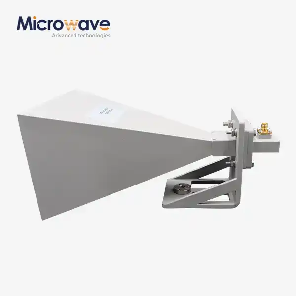 VIEW MOREWaveguide Horn Antennas
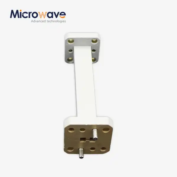 VIEW MOREWaveguide Straights and Transitions
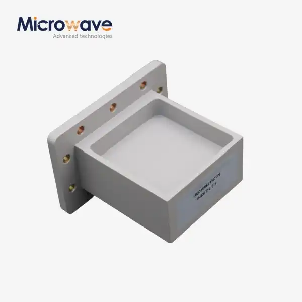 VIEW MORECustom WG to Coaxial Adapter
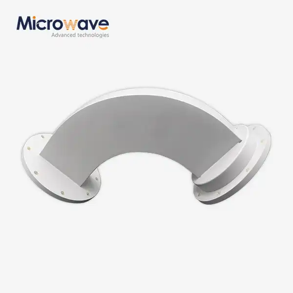 VIEW MOREWaveguide H Bend
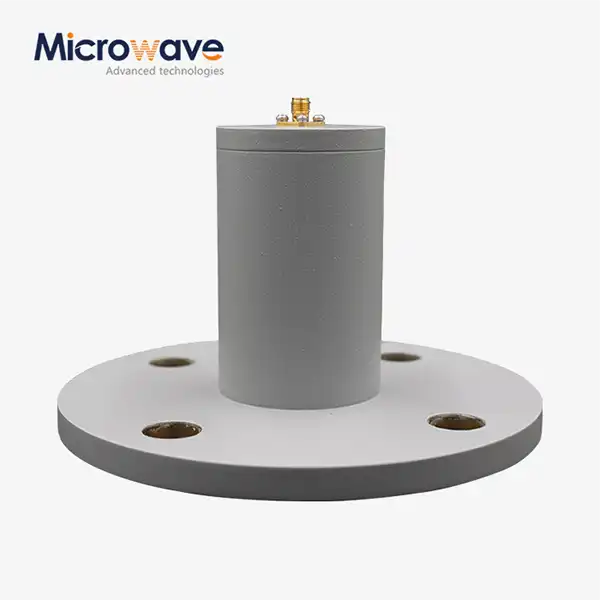 VIEW MORECircular Waveguide To Coaxial Adapter
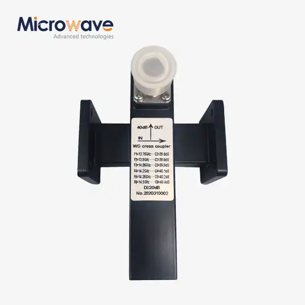 VIEW MORECrossguide Directional Coupler
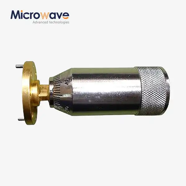 VIEW MOREWaveguide Sliding Short
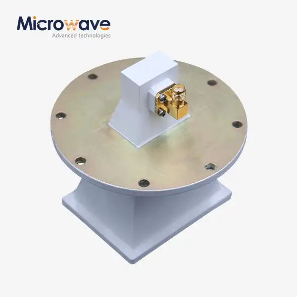 VIEW MOREPyramidal Linear Polarization Horn Antenna
