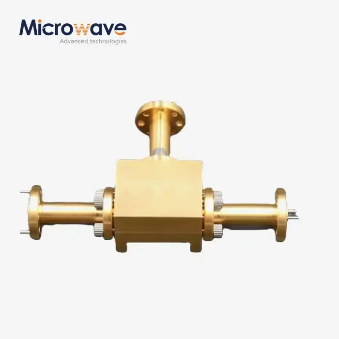
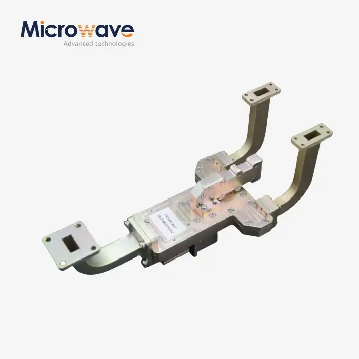
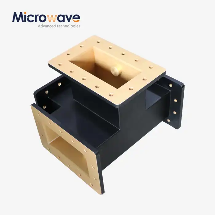
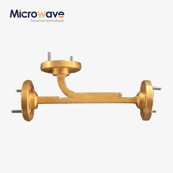
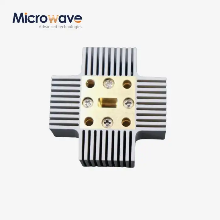
WG Low Pass Filter
WG Low Pass Filter for High-Power Microwave Systems — Precision Signal Filtering from C to Ka-Band
Advanced Microwave Technologies (ADM) designs and manufactures waveguide filters for the most demanding microwave environments in the C, X, Ku and Ka frequency ranges. Each WG Low Pass Filter is constructed from high-grade aluminium (6061-T6), copper, or brass — with optional silver or gold plating — and passes signals below a set cutoff frequency while attenuating those above it. The insertion loss in the passband is typically less than 0.1 dB and the stopband rejection is better than 60 dB up to the 3rd harmonic. Standard configurations are offered for custom designs to EIA waveguide sizes from WR-90 to WR-650.
What Is a WG Low Pass Filter?
A waveguide low pass filter is a passive RF component used in high-power microwave systems. It allows signals below a set cutoff frequency to pass through while blocking energy above that threshold.
Unlike coaxial alternatives, waveguide filters use the internal geometry of the waveguide structure — corrugated ridges, tapered ridges, or waffle-iron topologies — to achieve higher power handling and lower signal losses. Two practical problems these filters address are:
· Spurious harmonic suppression from high-power transmitters such as Klystrons or TWTAs, which can cause regulatory non-compliance
· Multipactor effect mitigation in vacuum or pressurized environments
This makes them relevant for radar transmitters, satellite uplinks, and deep-space communication networks.
Design Topologies and Construction Materials
ADM manufactures waveguide low pass filters in two main internal topologies.
The corrugated design utilises ridges that provide impedance steps to filter the basic mode. It is well suited for applications where compactness and minimal insertion loss are of primary concern.
The waffle-iron construction allows for transverse slots that suppress not only harmonics but also higher modes. This gives a larger stopband and is frequently utilised on the output stages of radar or high power transmitters.
Materials and Plating
Material Option | Application |
Aluminum 6061-T6 | Lightweight general-purpose applications |
Copper | High-conductivity, low-loss environments |
Brass | Durability-focused mechanical assemblies |
Silver Plating | Low insertion loss, preferred for passband performance |
Gold Plating | Corrosion resistance for naval or high-humidity environments |
Silver plating provides lower skin-depth loss due to its high conductivity. Gold plating offers better chemical stability in harsh outdoor or marine environments, though it carries slightly higher insertion loss.
Key Technical Specifications
Parameter | Specification |
Frequency Bands | C, X, Ku, Ka |
Insertion Loss (Passband) | Typically < 0.1 dB |
Stopband Rejection | > 60 dB (up to 3rd harmonic) |
VSWR | < 1.2:1 |
Power Handling (CW) | Kilowatt-level |
Power Handling (Peak) | Megawatt-level |
Waveguide Sizes | WR-90 to WR-650 (EIA standard) |
Compliance | MIL-DTL-85 environmental sealing |
Internal Edge Design | Rounded to reduce field concentration |
High-Power Performance and Arcing Prevention
Waveguide filters used in high-power systems must be designed in a way that keeps them from arcing. ADM makes sure that all of the inside edges have smooth shapes to lower the concentration of electromagnetic fields, which is the main reason why voltage breaks down.
To raise the dielectric breakdown threshold, the filter cavities can be purged with dry nitrogen or SF6 gas in systems that work under vacuum or pressure. This means that the filters can handle the highest power levels listed above, which are too high for planar or coaxial filter technologies to handle.
Application Scenarios
1. Satellite Communication (SATCOM) Uplinks
If you're at an Earth station, you put a WG Low Pass Filter after the High Power Amplifier (HPA). It lets the basic uplink frequency through, like Ku-band or Ka-band, but blocks harmonics that might mess up nearby satellites or receiver bands. These filters must also be able to work outside all day, even when the temperature changes every day.
2. High-Power Radar Systems
In defence radar and air traffic control radar, the filter is put at the output of the transmitter. It stops pulse emitters from sending out-of-band noise, which keeps the radar signal in the right range and stops it from arcing in high-pressure areas.
3. Medical Linear Accelerators (LINACs)
The filter is built into the RF distribution network of tools that treat cancer. It makes sure that only the desired drive frequency gets the structure that speeds things up. This keeps the magnetron safe from reflected harmonic energy in places with a lot of radiation.
Quality Control Process
ADM applies a multi-stage inspection and testing process to every waveguide filter before shipment.
S-Parameter Verification — Vector Network Analyzers (VNA) confirm that VSWR is within specification (< 1.2:1) and that harmonic rejection matches the agreed performance target.
High-Power Testing — Filters are tested under both continuous wave (CW) and peak power conditions to verify that no voltage breakdown or thermal runaway occurs.
Mechanical Inspection — Flange flatness and surface roughness are checked to prevent RF leakage and passive intermodulation (PIM).
Environmental Stress Screening (ESS) — Thermal shock and random vibration tests are conducted to simulate operational conditions over the product's service life.
Hermetic Leak Testing — For pressurized system filters, helium leak detection and 24-hour pressure decay monitoring confirm seal integrity and prevent moisture ingress that would degrade VSWR over time.
ADM's testing facility includes a 24-meter Microwave Darkroom with near-field and far-field measurement capabilities, covering frequencies from 0.5 GHz to 110 GHz.
Customization Options
ADM offers both standard and custom WG Low Pass Filter configurations. The number of internal iris and cavity sections is calculated to target a specific attenuation slope — for example, a custom design can be specified to achieve -60 dB attenuation at the 2nd harmonic frequency.
Custom options include:
· Specific cutoff frequency and rejection band
· Choice of waveguide flange standard
· Material and plating selection
· Pressurization port for gas-filled systems
· Custom packaging and labeling for OEM customers
If your application requires a configuration not shown here, please contact the ADM technical team with your frequency range, power level and rejection requirements to explore feasibility.
FAQ
Q: What is the main difference between waffle-iron and curved waveguide low pass filters in terms of how they are built?
A: Impedance stepping is done by ridges in corrugated designs, which mostly affects the fundamental mode. Waffle-iron designs have transverse slots that stop higher-order modes and make the stopband bigger, which is good for radar and high-power transmitter stages.
Q: How does the filter stop arcing when the power is high?
A: Internal sides that are rounded spread out electromagnetic fields. In environments with low or high pressure, the cavity can be filled with SF6 or dry nitrogen to raise the dielectric breakdown voltage threshold.
Q: Can the filter be changed to reject harmonics at a certain level?
A: Yes. To reach a certain attenuation slope, like -60 dB at the second harmonic frequency, the number of internal iris and cavity sections is worked out.
Q: How does the material used for finishing affect how well a filter works?
A: Silver plating lowers insertion loss because it is a very good conductor. Gold metal is used in places that are corrosive or wet, like the navy, even though it loses a little more signal.
Q: How is it proven that the hermetic seal can be used outside or under pressure?
A: Helium leak detection tests and 24-hour pressure decay tracking are done to make sure that the internal pressure stays the same and that moisture doesn't get in, which would hurt the performance of the VSWR.
Q: What sizes of waveguides can be used?
A: Waveguides with standard EIA sizes from WR-90 to WR-650 can be used. You can ask for custom waveguide lengths and flange types.
Contact Us
Send your specifications or custom design requirements for WG Low Pass Filter to craig@admicrowave.com. ADM's engineering team will respond with technical recommendations and a quotation.