


How to Customize Double-Ridged Waveguide Loop Couplers for Your Exact Frequency Needs?
In today's demanding microwave and RF landscape, engineers face the critical challenge of finding precise coupling solutions that match their exact frequency specifications. Whether you're developing satellite communication systems, radar applications, or advanced telecommunications infrastructure, the wrong Double-Ridged Waveguide Loop Coupler can lead to signal degradation, increased insertion loss, and system failures that cost both time and resources. The question isn't just about finding a coupler – it's about securing one that delivers optimal performance across your specific frequency range while maintaining the coupling accuracy and directivity your application demands. This comprehensive guide addresses the exact customization process that transforms a standard Double-Ridged Waveguide Loop Coupler into a precision-engineered solution tailored to your frequency requirements, helping you avoid costly mismatches and achieve superior system performance.
Understanding Double-Ridged Waveguide Loop Coupler Fundamentals
The Double-Ridged Waveguide Loop Coupler represents a sophisticated microwave component that combines the broadband capabilities of double-ridged waveguide technology with precision coupling mechanisms. Unlike traditional rectangular waveguides, the double-ridged design incorporates two opposing ridge structures that fundamentally alter the electromagnetic field distribution within the waveguide. This innovative approach significantly extends the operational frequency range while maintaining excellent electrical performance characteristics. The core architecture of a Double-Ridged Waveguide Loop Coupler consists of the double-ridged waveguide section integrated with a carefully designed coupling structure, typically featuring a loop or ring-shaped element. The double-ridged waveguide portion utilizes ridge structures that protrude into the waveguide cavity, effectively lowering the cutoff frequency and enabling operation across much broader frequency ranges than conventional rectangular waveguides. These ridges create a unique field configuration that supports stable propagation modes across wide bandwidths, making the Double-Ridged Waveguide Loop Coupler particularly valuable for applications requiring frequency agility or wideband performance. The coupling mechanism within the Double-Ridged Waveguide Loop Coupler operates through controlled electromagnetic interaction between the primary waveguide and the coupling port. The loop or ring structure is precisely positioned and dimensioned to extract a predetermined portion of the electromagnetic energy traveling through the main waveguide. The coupling strength depends on multiple factors including the loop size, position relative to the waveguide walls, and the specific ridge geometry. This coupling mechanism enables power sampling, signal monitoring, and power division functions while maintaining minimal impact on the primary signal path.
Critical Design Parameters
The performance characteristics of a Double-Ridged Waveguide Loop Coupler are determined by several interconnected design parameters that must be carefully optimized for specific frequency requirements. Ridge dimensions and spacing directly influence the waveguide's impedance characteristics and frequency response, while the coupling loop geometry determines the coupling coefficient and directivity performance. The relationship between these parameters becomes particularly critical when customizing the coupler for narrow frequency bands or specific coupling requirements. Ridge height and width ratios affect the characteristic impedance and field distribution within the Double-Ridged Waveguide Loop Coupler. Taller ridges generally provide broader bandwidth capabilities but may introduce higher insertion loss at certain frequencies. The ridge separation distance influences the TEM-like mode propagation characteristics that give double-ridged waveguides their superior bandwidth performance. These geometric relationships must be precisely calculated and optimized based on the target frequency range and performance specifications. The coupling loop design parameters include loop diameter, wire thickness, positioning within the waveguide, and orientation relative to the electric and magnetic field patterns. Loop position affects both coupling strength and frequency response, while the loop material and construction influence power handling capability and thermal stability. For customized Double-Ridged Waveguide Loop Coupler solutions, these parameters are individually optimized through electromagnetic simulation and empirical testing to achieve the desired performance characteristics.

Frequency-Specific Customization Strategies
Customizing a Double-Ridged Waveguide Loop Coupler for specific frequency requirements involves a systematic approach that begins with comprehensive frequency response analysis and performance specification development. The customization process must account for the unique propagation characteristics of double-ridged waveguides across different frequency ranges, as the coupling mechanism behavior varies significantly with frequency due to the wavelength-dependent nature of electromagnetic interactions. For lower frequency applications, typically below 6 GHz, the Double-Ridged Waveguide Loop Coupler design focuses on achieving adequate coupling strength while maintaining acceptable directivity performance. The larger wavelengths at these frequencies require carefully sized coupling loops to ensure sufficient electromagnetic interaction without creating unwanted resonances or impedance discontinuities. Ridge dimensions must be optimized to support stable propagation modes while providing the necessary bandwidth coverage for the target frequency range. Mid-frequency applications, ranging from 6 GHz to 18 GHz, present unique challenges for Double-Ridged Waveguide Loop Coupler customization due to the transition between different propagation mode behaviors. The coupling mechanism must be designed to maintain consistent performance across this broad frequency range while accommodating the changing field distributions that occur as frequency increases. Ridge geometry optimization becomes critical for maintaining stable impedance characteristics and minimizing insertion loss variations across the frequency band.
High-Frequency Optimization Techniques
High-frequency customization of Double-Ridged Waveguide Loop Couplers, particularly above 18 GHz, requires specialized design approaches that account for the increased sensitivity to dimensional tolerances and material properties. At these frequencies, even minor variations in ridge geometry or coupling loop positioning can significantly impact performance, making precision manufacturing and quality control essential for successful customization. The coupling loop design for high-frequency Double-Ridged Waveguide Loop Coupler applications must consider the reduced wavelengths and increased field concentration effects that occur at millimeter-wave frequencies. Smaller loop dimensions are generally required to maintain appropriate coupling coefficients, but the reduced size also increases manufacturing complexity and tolerance sensitivity. Advanced electromagnetic simulation tools become indispensable for optimizing these designs and predicting performance across the target frequency range. Material selection plays an increasingly important role in high-frequency Double-Ridged Waveguide Loop Coupler customization, as conductor losses and dielectric effects become more pronounced at millimeter-wave frequencies. High-conductivity materials such as silver or gold plating may be necessary to minimize insertion loss, while careful attention to surface roughness and contact resistance becomes critical for maintaining performance specifications.
Advanced Coupling Control Methods
The ability to precisely control coupling characteristics represents a fundamental advantage of customized Double-Ridged Waveguide Loop Coupler solutions. Unlike fixed coupling devices, customized couplers can be designed with specific coupling coefficients, directivity performance, and frequency response tailored to exact application requirements. This level of control enables system designers to optimize overall performance while minimizing component count and system complexity. Variable coupling control in Double-Ridged Waveguide Loop Coupler designs can be achieved through multiple approaches, including adjustable loop positioning, variable loop geometry, and electronically controlled coupling mechanisms. Mechanical adjustment systems allow for post-installation coupling optimization, while fixed customized designs provide optimal performance for known operating conditions. The choice between variable and fixed coupling control depends on application requirements, cost considerations, and operational complexity constraints. Electronic coupling control methods represent the most sophisticated approach to Double-Ridged Waveguide Loop Coupler customization, utilizing active components or variable reactance elements to dynamically adjust coupling characteristics. These systems can provide real-time optimization of coupling performance based on operating conditions or system requirements, but require additional complexity and power consumption. The integration of electronic control systems with the basic Double-Ridged Waveguide Loop Coupler structure requires careful design to maintain RF performance while accommodating the control electronics.
Directivity Enhancement Techniques
Directivity performance represents a critical parameter for many Double-Ridged Waveguide Loop Coupler applications, particularly in measurement systems and applications requiring precise signal monitoring capabilities. Customization techniques for enhancing directivity include optimized loop positioning, multiple coupling elements, and compensation network integration. These approaches can significantly improve directivity performance beyond standard coupler specifications. The loop positioning within the Double-Ridged Waveguide Loop Coupler structure directly affects directivity performance, with optimal positioning determined by the specific frequency range and waveguide geometry. Advanced customization techniques utilize multiple coupling elements positioned at precise locations to cancel unwanted coupling while enhancing desired signal extraction. This approach requires sophisticated design analysis but can achieve directivity improvements of 10 dB or more compared to standard configurations. Compensation network integration provides another approach to directivity enhancement in customized Double-Ridged Waveguide Loop Coupler designs. These networks, typically implemented as reactive elements or transmission line sections, are designed to cancel unwanted coupling components while preserving desired signal extraction. The design and implementation of these compensation networks requires detailed electromagnetic analysis and careful manufacturing control to achieve the predicted performance improvements.
Material Selection and Manufacturing Considerations
The selection of appropriate materials for customized Double-Ridged Waveguide Loop Coupler applications involves balancing electrical performance, mechanical stability, environmental requirements, and cost considerations. Different applications may require specialized materials to achieve optimal performance, particularly for extreme environmental conditions or high-power applications. The material selection process must consider both the waveguide structure and coupling elements, as each may have different performance requirements. Conductor materials for the waveguide structure typically include aluminum, brass, or copper alloys, each offering different advantages for specific applications. Aluminum provides excellent conductivity-to-weight ratios and corrosion resistance, making it suitable for aerospace and mobile applications. Brass offers superior machinability and dimensional stability, while copper alloys provide the highest conductivity for applications requiring minimal insertion loss. The choice of conductor material affects both electrical performance and manufacturing processes for the Double-Ridged Waveguide Loop Coupler. Surface treatment and plating options provide additional customization opportunities for Double-Ridged Waveguide Loop Coupler applications. Silver plating offers the highest conductivity and is particularly beneficial for high-frequency applications, while gold plating provides superior corrosion resistance and contact stability. For harsh environment applications, specialized coatings or passivation treatments may be necessary to ensure long-term reliability and performance stability.
Manufacturing Precision Requirements
The manufacturing precision requirements for customized Double-Ridged Waveguide Loop Coupler designs depend heavily on the target frequency range and performance specifications. Higher frequency applications generally require tighter dimensional tolerances to maintain performance specifications, while broadband applications may be more forgiving of manufacturing variations. Understanding these tolerance requirements is essential for balancing performance and manufacturing cost considerations. Ridge geometry precision represents one of the most critical manufacturing requirements for Double-Ridged Waveguide Loop Coupler production. Ridge height and width dimensions typically require tolerances of ±0.001 inches or better for high-frequency applications, while ridge surface finish can significantly impact performance at millimeter-wave frequencies. Advanced machining techniques, including CNC milling and electrical discharge machining (EDM), may be necessary to achieve the required precision levels. Coupling loop manufacturing precision requirements vary with the specific coupling mechanism and target performance specifications. Wire loop couplers require precise positioning and consistent loop geometry, while printed circuit coupling elements demand accurate substrate processing and metallization control. The manufacturing approach must be selected based on the specific design requirements and production volume considerations for each customized Double-Ridged Waveguide Loop Coupler application.
Performance Optimization and Testing
Comprehensive performance testing represents an essential component of the customization process for Double-Ridged Waveguide Loop Coupler applications. The testing protocol must verify all critical performance parameters across the target frequency range while ensuring compliance with application-specific requirements. Advanced testing capabilities, including vector network analysis and specialized measurement techniques, are typically required to fully characterize customized coupler performance. Coupling coefficient measurement across the target frequency range provides fundamental performance verification for customized Double-Ridged Waveguide Loop Coupler designs. This measurement requires precision calibration and careful attention to measurement system limitations, particularly for high-frequency applications where measurement uncertainties can significantly impact results. The measurement setup must be designed to minimize the impact of connectors, cables, and other system components on the measurement accuracy. Directivity performance testing requires specialized measurement techniques that can accurately separate forward and reverse coupling components. This testing typically involves precision phase measurements and may require specialized test fixtures to achieve adequate measurement accuracy. The directivity measurement results provide critical information about the coupling mechanism effectiveness and can identify potential design improvements for future customization efforts.
Conclusion
Successfully customizing Double-Ridged Waveguide Loop Couplers for exact frequency needs requires a comprehensive understanding of waveguide physics, coupling mechanisms, and manufacturing precision. The process involves careful optimization of ridge geometry, coupling element design, material selection, and manufacturing processes to achieve the desired performance characteristics across specific frequency ranges.
Cooperate with Advanced Microwave Technologies Co., Ltd.
Advanced Microwave Technologies Co., Ltd stands as your trusted China Double-Ridged Waveguide Loop Coupler manufacturer, offering over 20 years of expertise in precision microwave solutions. Our state-of-the-art 24m Microwave Darkroom enables comprehensive testing from 0.5-110 GHz, ensuring every customized Double-Ridged Waveguide Loop Coupler meets your exact specifications. As a leading China Double-Ridged Waveguide Loop Coupler supplier, we provide ISO-certified, RoHS-compliant solutions for satellite communications, defense, aerospace, and telecommunications applications. Our China Double-Ridged Waveguide Loop Coupler factory delivers High Quality Double-Ridged Waveguide Loop Coupler products with competitive Double-Ridged Waveguide Loop Coupler prices through efficient manufacturing processes. Whether you need China Double-Ridged Waveguide Loop Coupler wholesale quantities or specialized OEM solutions, our expert engineers provide comprehensive technical support from prototyping to full-scale production. Contact us today at craig@admicrowave.com for your Double-Ridged Waveguide Loop Coupler for sale inquiries and discover why industry leaders choose Advanced Microwave Technologies Co., Ltd for their critical microwave component needs.
FAQ
Q: What frequency range can be achieved with customized Double-Ridged Waveguide Loop Couplers?
A: Customized Double-Ridged Waveguide Loop Couplers can operate from 0.5 GHz to 110 GHz, with specific frequency ranges optimized based on ridge geometry and coupling design requirements.
Q: How long does the customization process typically take for Double-Ridged Waveguide Loop Couplers?
A: The customization timeline ranges from 2-6 weeks depending on complexity, including design optimization, prototyping, and testing phases for optimal performance verification.
Q: What coupling values are available for customized Double-Ridged Waveguide Loop Couplers?
A: Standard coupling values range from 10 dB to 60 dB, with custom coupling coefficients available to meet specific application requirements and system integration needs.
Q: Can Double-Ridged Waveguide Loop Couplers be customized for high-power applications?
A: Yes, customization includes power handling optimization through material selection, thermal management design, and coupling mechanism sizing to handle power levels from watts to kilowatts.
References
1. "Microwave Engineering Fundamentals and Applications" by David M. Pozar, John Wiley & Sons
2. "Waveguide Components for Antenna Feed Systems: Theory and CAD" by Jarmo Juntunen, Artech House Publishers
3. "RF and Microwave Coupling Applications" by IEEE Microwave Theory and Techniques Society, IEEE Press
4. "Advanced Waveguide Technology for Communications Systems" by Robert S. Elliott, Academic Press
YOU MAY LIKE
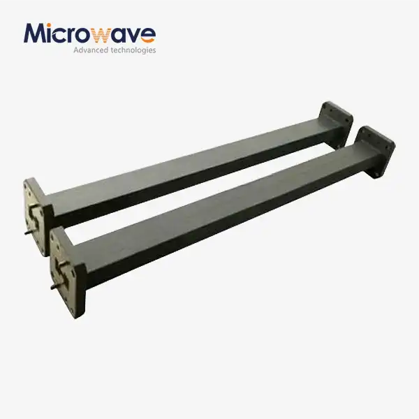 VIEW MOREDouble Ridge Straight Waveguide
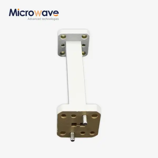 VIEW MOREDouble Ridge Waveguide Transition
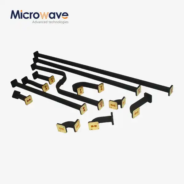 VIEW MOREDouble Ridged Flexible Waveguide
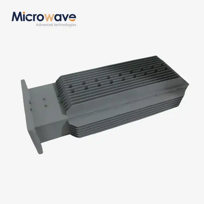 VIEW MOREDouble Ridge Waveguide Load
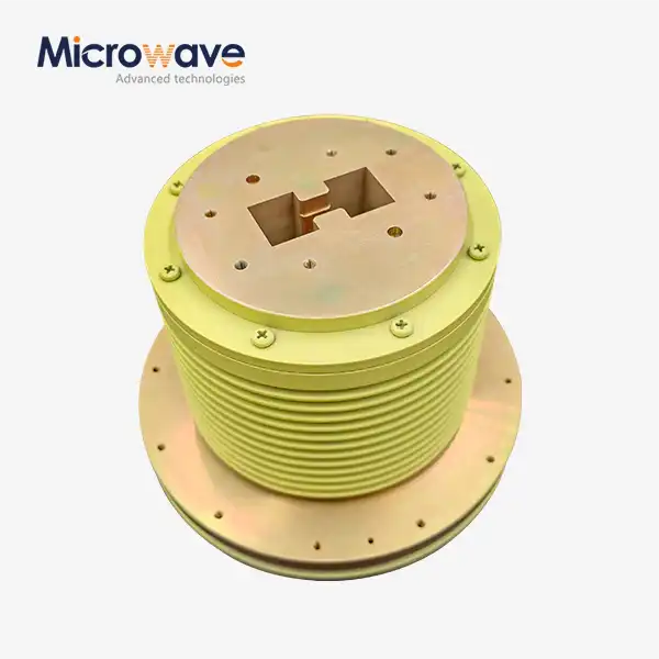 VIEW MOREDouble Ridge Waveguide Rotary Joint
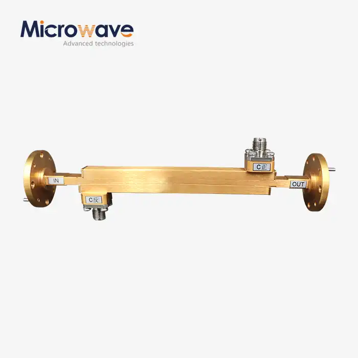 VIEW MOREDouble-Ridged Waveguide Broadwall Directional Coupler
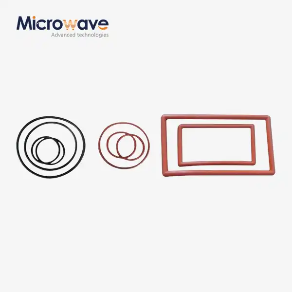 VIEW MOREWaveguide Flange Gasket
 VIEW MOREWaveguide Adjustable Support
