





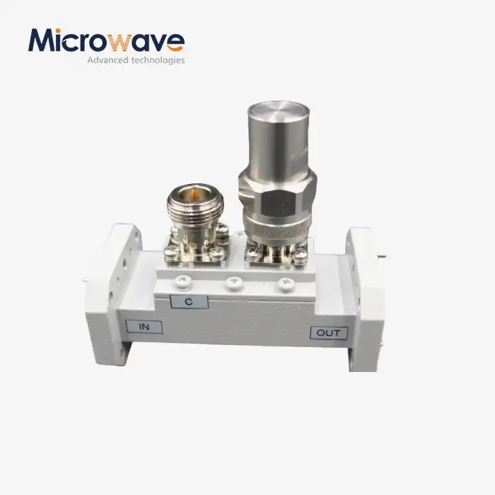
Double-Ridged Waveguide Loop Coupler
Double-Ridged Waveguide Loop Coupler for Broadband RF Systems
Advanced Microwave Technologies' (ADM) Double-Ridged Waveguide Loop Coupler is a passive microwave part made for wide-band uses where regular rectangular waveguide couplers don't work well. By using metallic ridges inside to lower the dominant mode's cutoff frequency, it can work across multiple octave bandwidths, like 2.4:1 or 3.6:1 ratios, while keeping a coupling factor of 30 to 60 dB, a flatness deviation of ±1.0 dB, and a directivity of more than 18 dB even at the edges of the band.
What Is a Double-Ridged Waveguide Loop Coupler?
A product is an inactive RF part that is used to sample or add energy to a transmission line with two ridges. The loop probe, which is attached to the waveguide's wide wall, magnetically connects with the wave's H-field. This lets power monitoring, source levelling, and signal injection happen without a lot of insertion loss or changes to the main line VSWR.
The double-ridged structure has two internal ridges that are at right angles to each other. These ridges change the electromagnetic field inside the guide, which lowers the dominant mode's cutoff frequency and increases the working bandwidth well beyond what is normally possible in a waveguide. The position, size, and shape of the loop directly affect how well it couples, including how flat and straight it is across the whole band.
The small size of the part suits the wide bandwidths needed by Electronic Countermeasure (ECM) and broadband radar systems. It has input, output, and coupling ports.
Key Technical Specifications
Parameter | Specification |
Waveguide Series | WRD-180, WRD-650, WRD-750 (MIL-DTL-85) |
Operating Bandwidth | Multi-octave (e.g., 2.4:1 or 3.6:1 ratio) |
Typical Frequency Range | 6–18 GHz, 18–40 GHz (application-dependent) |
Coupling Factor | 30 dB to 60 dB |
Coupling Flatness | ±1.0 dB across full band |
Directivity | >18 dB at band edges |
Insertion Loss | <0.1 dB (main line) |
Main Line VSWR | <1.10:1 to 1.15:1 |
Peak Power Handling | Kilowatt range (pressurization-dependent) |
Material | Aluminum 6061-T6 or Copper alloy, silver-plated |
Thermal Shock Range | -55°C to +85°C (MIL-STD-202) |
Pressurization Support | SF6 or dry air with sealed dielectric loop support |
Design and Material Construction
This coupler is made by ADM from aluminium 6061-T6 or copper alloys. It is silver-plated to lower ohmic losses at the contact surfaces. The measurements are all within the limits set by MIL-DTL-85, which controls the shape of a double-ridged waveguide.
The loop probe has a dielectric support structure that has been tested and approved by MIL-STD-202 Thermal Shock to make sure it stays together during quick temperature changes from -55°C to +85°C. Because the compact loop form factor is smaller than multi-hole branch-line couplers, it can be used on airborne platforms that need to be light.
Performance Compared to Standard Couplers
Standard rectangular waveguide couplers work with bandwidth ratios of less than 1.5:1, and they often lose coupling at the edges of the bands they work with. This is exactly what the Double-Ridged Waveguide Loop Coupler does with its ridged structure and loop shape.
Coupling flatness stays within ±1.0 dB across multiple octave bands, which is a level of consistency that regular couplers can't keep up at the same bandwidth. At the edges of the band, directivity is higher than 18 dB, so forward and reverse power are reliably separated across the whole working range.
The main line insertion loss stays below 0.1 dB, which protects the integrity of the signal in the main transmission path. The main line VSWR stays below 1.15:1, which keeps echoes to a minimum in high-power setups.
Application Scenarios
Airborne Electronic Warfare (EW) Pods
This coupler checks the output of Travelling Wave Tube Amplifiers (TWTAs) in airborne environments with a lot of vibration and limited space. It does this across bands like 6–18 GHz or 18–40 GHz. It makes sure that the blocking signals are sent at the right power levels so that the source amplifier isn't overworked.
SATCOM Stations on the Ground
This coupler is used by multi-band satellite ground station transmitters as a precise sampling point for Automatic Level Control (ALC) feedback loops. It keeps the uplink power stable when changes in the atmosphere cause signal changes.
Labs for High-Power EMC Testing
In radiated immunity test chambers, EMC engineers use this coupler to keep an eye on the strength of incident fields. Because the ridged waveguide has a wide working bandwidth, you don't have to switch out hardware as often between frequency sweeps.
Quality Control Process
Each unit goes through the following verification steps before shipment.
Vector Network Analyzer (VNA) Sweep — confirms coupling flatness, insertion loss (<0.1 dB), and main line VSWR (<1.10:1 or 1.15:1) across the full specified frequency band.
CMM (Coordinate Measuring Machine) Inspection — measures flange tolerances to confirm air-tight mating for pressurized waveguide systems.
MIL-STD-202 Thermal Shock Testing — validates that the dielectric loop support does not fracture under rapid temperature shifts between -55°C and +85°C.
High-Pot (Dielectric Withstanding Voltage) Testing — confirms that the loop probe will not arc under peak power conditions representative of radar pulse environments.
Customization and Supply
ADM supports custom configurations for Double-Ridged Waveguide Loop Coupler based on system requirements. Waveguide series, coupling factor, connector interface, and flange type can all be specified.
Some designs allow minor loop probe depth adjustments post-assembly, enabling fine-tuning of coupling by ±1–2 dB during final system integration. Pressurization-compatible versions with sealed dielectric supports are available for airborne and high-altitude deployments.
ADM's testing capability covers 0.5 GHz to 110 GHz, supported by a 24-meter microwave darkroom and an Antenna Plane Near and Far Field Measuring Recombination Chamber.
FAQ
Q: What is the difference between coupling flats and regular directional couplers?
A: Loop couplers in ridged guides are designed to work well across a wide range of frequencies, staying flat within ±1 dB across many octave bands. Standard rectangular couplers don't work as well at the edges of bands and can't match this level of consistency at the same bandwidth ratio.
Q: Can these couplers work in waveguide environments with pressure?
A: Waveguide pressurisation can be kept up with SF6 or dry air in units with sealed dielectric loop supports or pressure windows. This stops corona discharge at high altitudes.
Q: What changes how well directivity works?
A: The directionality depends on how well the loop is shaped and how much resistance there is at the end of the secondary arm. Small flaws in the manufacturing process can make it harder for forward and reflected waves to be separated. This is why CMM inspection is part of the quality control process.
Q: Can the binding factor be changed after it has been made?
A: The coupling factor is set at the factory for fixed-loop designs. Some designs let you make small changes to the loop probe depth to finetune coupling by ±1–2 dB when the whole system is put together.
Q: What is the most common way for high-power systems to fail?
A: Arcing at the loop tip or dielectric window is the most common failure. It's caused by too many peak voltage standing waves. As part of ADM's quality control, high-pot testing is always done to look for this risk.
Q: What waveguide standards does ADM's coupler meet?
A: ADM makes products that meet MIL-DTL-85 standards. These include waveguide series WRD-180, WRD-650, and WRD-750. Custom designs for the series can be made upon request.
Contact Us
Send your frequency range, coupling factor, and application details for the Double-Ridged Waveguide Loop Coupler to craig@admicrowave.com and ADM's engineering team will follow up with a suitable configuration.
YOU MAY LIKE
 VIEW MOREDouble Ridge Straight Waveguide
 VIEW MOREDouble Ridge Waveguide Bend
 VIEW MOREDouble Ridge Twist Waveguide
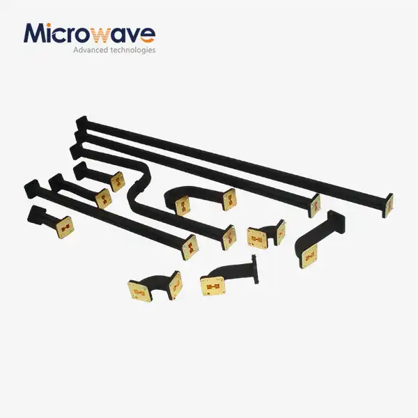 VIEW MOREDouble Ridged Flexible Waveguide
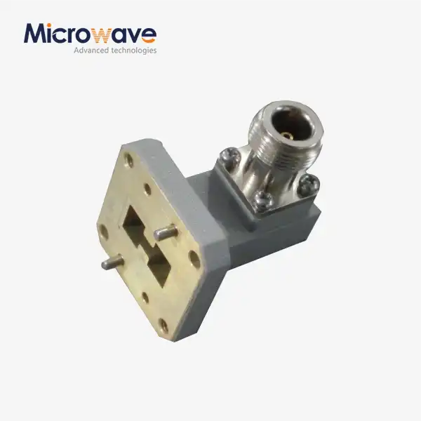 VIEW MOREDouble Ridged WG To Coaxial Adapter
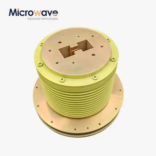 VIEW MOREDouble Ridge Waveguide Rotary Joint
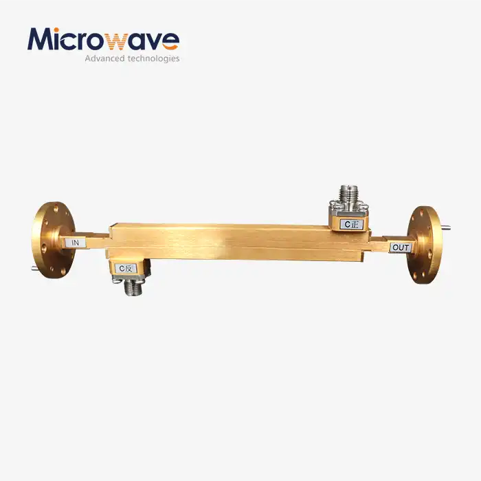 VIEW MOREDouble-Ridged Waveguide Broadwall Directional Coupler
 VIEW MOREDouble Ridge Waveguide Tube
