





Waveguide Cable Assembly Bend Radius and Routing Rules Explained
When engineers talk about signal integrity in high-frequency systems, bend radius rarely gets the attention it deserves — until something goes wrong. A waveguide cable assembly is not a conventional cable that you can reroute freely. It operates in TE or TM propagation modes inside a precisely dimensioned hollow conductor, meaning any geometric distortion directly translates into electrical performance degradation. Whether you're integrating assemblies into a radar enclosure, a satellite ground station, or a 5G millimeter-wave test bench, understanding bend radius and routing rules is not optional — it's foundational.
Understanding Waveguide Cable Assembly Bend Radius
What Bend Radius Actually Means
The bend radius tells you the least amount of curvature that a waveguide cable assembly can take before its internal geometry becomes forever changed. The cross-sectional regularity of the hollow conductor is thrown off when the convoluted core, which is usually overlapping strips of silver-plated copper or brass, is deformed. This leads to VSWR spikes, high insertion loss, and, in the worst cases, mechanical damage that can't be fixed. As an example, the smallest bend radius (MBR) for a WR-75 bendable unit is usually around 65 mm. Even going over this limit once can cause VSWR problems that may be hard for normal field tests to find.
Static vs. Dynamic Bend Radius
In different building situations, these two factors are useful. It's called "static MBR" when the part is directed and held in place. Dynamic MBR is a bigger, more conservative number that is used when the assembly bends over and over while it's working, like in a gimbal system or a spinning antenna mount. Engineers often don't notice this difference and define only a static MBR when a dynamic application is really what is wanted. Before committing to a route plan, you should always check both numbers against the datasheet.
How Material and Frequency Interact
Composition has a direct effect on how bendable a material is. Aluminum waveguide walls are lighter than copper or stainless steel ones, but they are less flexible. At higher frequencies, like Ka-band (26.5–40 GHz) and above, waveguide dimensions get smaller, which means wall thickness goes down, and the sensitivity to distortion caused by bends goes up. It is very important for phased array radar and vector network analyzer (VNA) calibration setups that the phase stays stable when they bend, which is usually specified within ±2° to ±5° for premium assemblies.
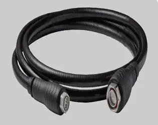
Essential Routing Rules for Waveguide Cable Assemblies
It takes more care to route a flexible waveguide cable assembly than it does to route a regular RF coaxial wire. These parts carry strong signals in controlled mode conditions, and any problem with the mechanics causes RF performance loss at the system level. The tips below are what the industry recommends for setups that will last for a long time and work well.
- Maintain MBR throughout the entire cable run. Keep the MBR constant throughout the whole cable run. Do not let any part of the unit go below the minimum bend radius that was given, not even at the ends that are close to the flanges. Some of the most common reasons why an assembly fails too soon are stress buildup near the points where two connectors meet.
- Avoid compression loading. Do not use compression loading. It is not recommended for waveguide cable systems to hold structural weight or be run through conduit areas that put radial pressure on them. The complex core gets deformed when compressed, and insertion loss goes up across the band.
- Account for thermal expansion. Take into account how heat expands. Changing the temperature from −55°C to +85°C causes measurable changes in the size of things outside, like satellite earth stations, naval systems, or flight platforms. Allow some room for movement in the routing path so that this movement is taken care of without putting mechanical stress on the flanges.
- Secure at regular intervals. Secure on a regular basis. Use soft-lined clamps or saddle mounts at intervals that are right for the size and weight of the assembly. Acoustic or structural excitation makes unsupported spans vibrate, which speeds up fatigue in the interlocking core.
These methods are not just ideas; they are based on what has been learned from defense radar projects, building SATCOM infrastructure on the ground, and high-frequency test labs where one broken part can ruin a whole measurement campaign.
Technical Specifications and Design Principles Relevant to Bend Radius
Material Selection and Its Mechanical Implications
Copper-based cores are the most common choice for lab and flying uses because they have the best conductivity and flex life. Stainless steel jacketing makes the material more durable in outdoor and marine settings, but it also raises the MBR because it is less flexible. Aluminum construction lowers the weight of aircraft bases that need to be light, but it needs stricter bend limits. Choosing the wrong material for your temperature and mechanical surroundings is a mistake that you don't notice until after the job is done.
Design Parameters That Drive Custom Assembly Geometry
When you ask for a special waveguide cable assembly, the bend radius is determined by the wall thickness, waveguide size (WR name), jacket material, and flange standard (CPR, UG, or UBR). The size limits for a WR-28 Ka-band assembly are tighter than those for a WR-137 C-band assembly. This means that unique routing geometry needs to be modeled before it can be made. During the RFQ stage, ADM's engineering team works directly with procurement professionals to make sure that routing paths work with the company's mechanical and electrical constraints.
Comparison and Decision-Making: Choosing the Right Waveguide Cable Assembly
Below 18 GHz, coaxial lines are the most common because they are easy to route and don't take up much space. Insertion loss in coaxial configurations is too high above 18 GHz, especially at 40 GHz and higher. The insertion loss of a waveguide cable assembly at 40 GHz is about one-tenth that of a similar coaxial cable assembly. It can also handle a lot more continuous wave power.
Overall, rigid waveguide plumbing has the lowest insertion loss and can't handle any positional displacement. In exchange for being able to bend mechanically, flexible waveguide assemblies have a little more loss. This is a trade-off that makes sense in most system integration situations. Twistable parts go even further by allowing axial movement. This is useful for multi-axis gimbal mounts but makes the design a little more complicated and costs a little more.
The choice is easy: a flexible waveguide cable assembly is the best option if your application needs to send high power above 18 GHz while also being mechanically flexible in a controlled setting. If the standard is based on weight and weather exposure, then the choice of material and jacket type becomes the main things that set them apart.
Procurement Guide for Waveguide Cable Assemblies: What You Need to Know
When they look at the RFQ package, procurement engineers who work on defense, SATCOM, or industrial RF projects should see the bend radius standard as a must-have, not a suggestion. Mission-critical programs should not be supported by suppliers who can't give them both static and dynamic MBR data, VNA sweep test results, and phase stability curves under flexure.
Custom waveguide cable assemblies have lead times that depend on the WR size, flange design, and jacket standard. For engineered-to-order builds, these times are usually between two and six weeks. When the supply chain gets tight, bulk procurement agreements can help keep manufacturing slots open and lower the cost per unit. When looking for things for any regulated purpose, ISO 9001:2015 certification and RoHS compliance should be basic needs, not extras.
Conclusion
Bend radius and routing discipline are not just nice-to-haves; they are the technical foundations on which the purity of the RF signal depends. Waveguide cable assembly performance is maintained throughout its entire operating lifecycle by specifying the correct minimum bend radius, choosing the right materials, and routing parts within the limits set by engineers. These rules work for all kinds of situations, like airborne radar, a Ka-band SATCOM earth station, or a millimeter-wave test environment. Most problems in the field can be avoided by working with a maker who is highly skilled from the beginning of the specification process.
FAQ
What happens if I bend the metal more than the minimum radius?
Going over the MBR permanently changes the shape of the interlocking, complicated core. This makes the hollow conductor less smooth, which leads to VSWR spikes and higher insertion loss across the operating band. In situations with a lot of power, these breaks can also cause limited arcing.
Can flexible waveguide assemblies handle tight routing in compact enclosures?
Yes, but only in the changeable MBR they set. Even though they have a small insertion loss cost, flexible designs can handle complicated routing lines that rigid plumbing can't. Before you order, you should always make sure that the MBR of the waveguide cable assembly matches your tightest routing turn.
How do I let a supplier know about my routing needs?
Give a sized routing plan, say whether it will be used statically or dynamically, list the working frequency band, the flange standard, and the environmental conditions. A good waveguide cable assembly maker will check your route shape and let you know if there are any problems before they start making the cable.
Are the requirements for phase stability the same for all suppliers?
No, phase stability under flexure depends on how the core is designed and how well it is made. For VNA and phased array uses, ask for parts that have a phase difference of ±5° or better and test data to make sure they meet the requirements.
Partner with ADM for Precision Waveguide Cable Assembly Solutions
For more than 20 years, ADM has provided engineered waveguide cable assemblies to research, military, and SATCOM projects around the world. Before it is shipped, every assembly goes through full-band VNA testing, flange planarity checking, and phase stability proof. Trusted waveguide cable assembly maker with ISO 9001:2015 and RoHS certifications, ADM makes custom solutions that fit your exact bend radius and routing needs. To get a price, email our experts at craig@admicrowave.com.
References
1. IEEE Transactions on Microwave Theory and Techniques — IEEE, 2021
2. Microwave Engineering, David M. Pozar — Wiley, 4th Edition, 2011
3. MIL-DTL-3922: Flexible Waveguide, Military Specification — U.S. Department of Defense, 2005
4. IEC 62037: Passive RF and Microwave Devices, Intermodulation Level Measurement — International Electrotechnical Commission, 2012
5. ROHN Industries RF Systems Engineering Handbook — ROHN Industries, 2018
6. Waveguide Handbook, Nathan Marcuvitz — IET Electromagnetic Waves Series, Reprint Edition, 1986
YOU MAY LIKE
 VIEW MOREWG Transition
 VIEW MORECircular Waveguide Transition
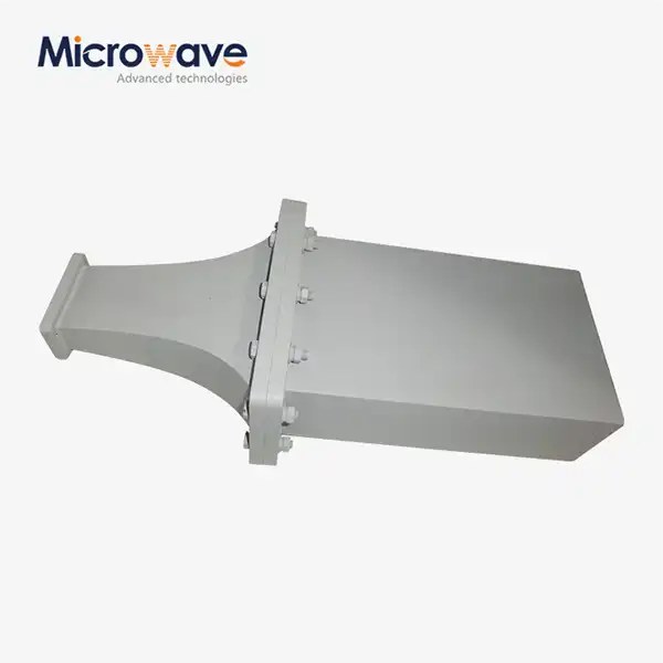 VIEW MOREDouble Ridge Waveguide Termination
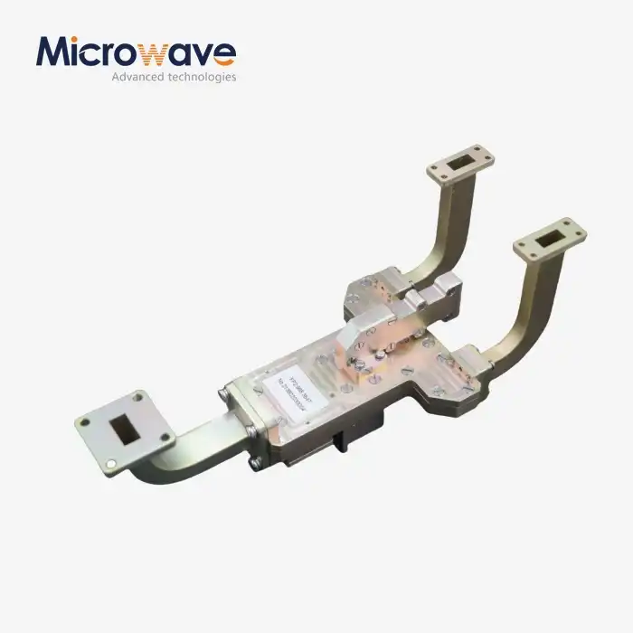 VIEW MOREMagic Hybrid Tee
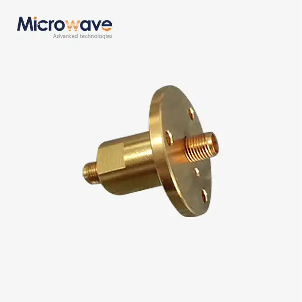 VIEW MORESingle Channel Coaxial Rotary Joint
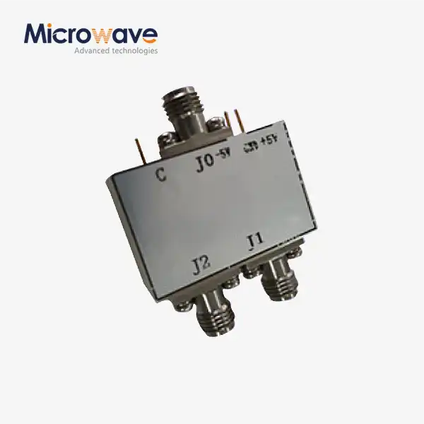 VIEW MOREHigh Power Coaxial Switch
 VIEW MOREMMDS Transmitting Antenna
 VIEW MORELadder Membrane Conical Dual circular Polarization Horn Antenna
