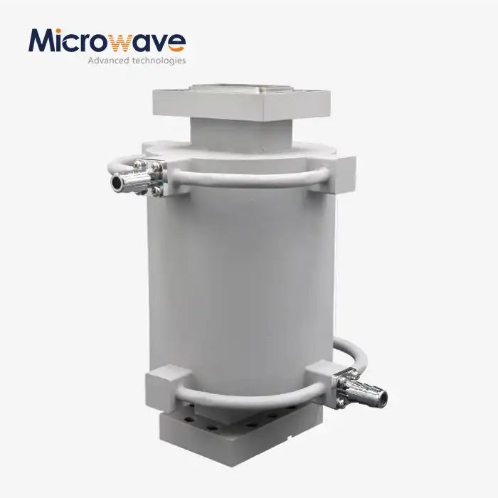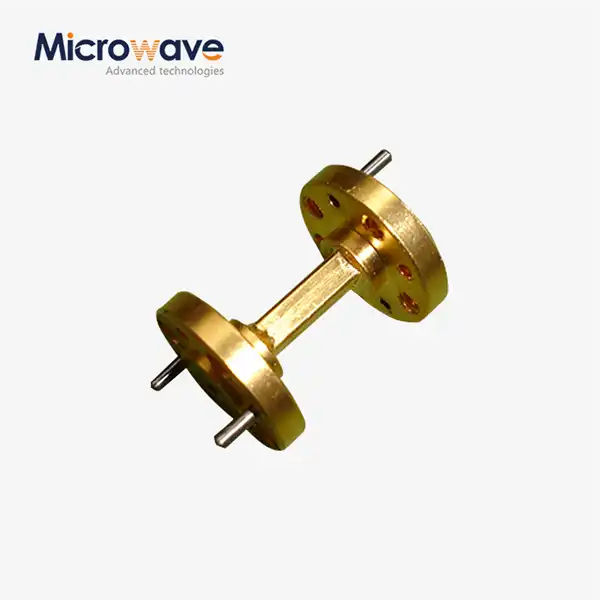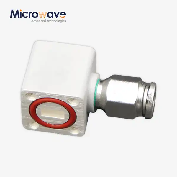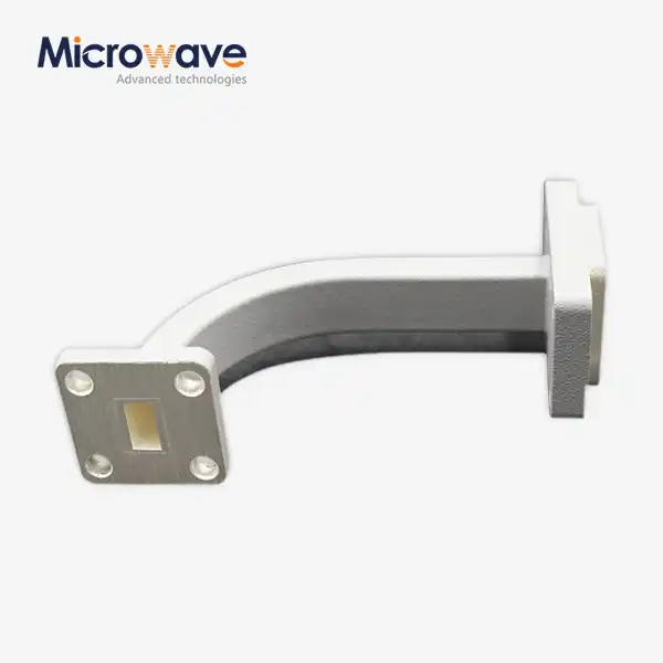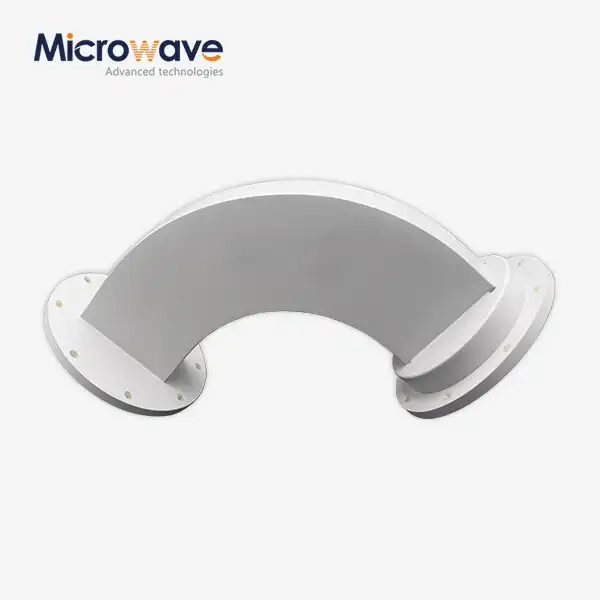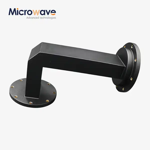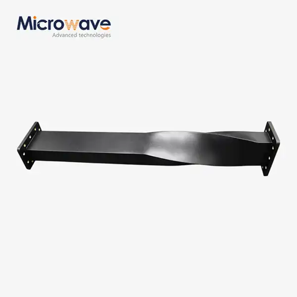
Waveguide Twist
Waveguide Twist for Radar and SATCOM Systems
In waveguide system integration, polarisation mismatch is a problem that keeps coming up. RF energy can't move easily between two flanges that are physically orthogonal, which leads to return loss and system failure. This problem can be fixed with a Waveguide Twist, which physically rotates the waveguide cross-section and realigns the electric field vector between parts that don't match. ADM makes cross-band step and continuous twist setups from WR-90 (X-Band) to WR-28 (Ka-Band), with VSWR at or below 1.10:1 and insertion loss below 0.1 dB.
What a Waveguide Twist Does
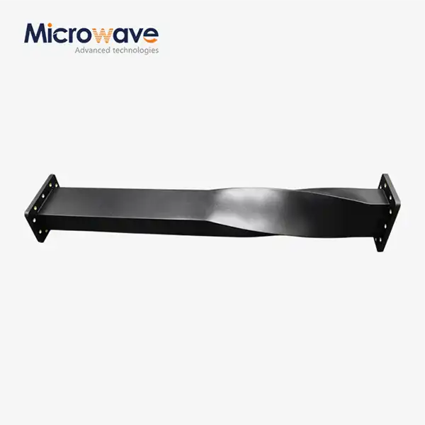
For example, to connect an antenna feed that is vertically polarised to a transmitter output that is horizontally polarised, the TE10 mode needs to be realigned without changing the actual direction of the transmission. This is taken care of by turning the waveguide cross-section along its length, either quickly through impedance steps or gradually through a tapered profile. This makes sure that the electric field vector is in the right place at the output flange.
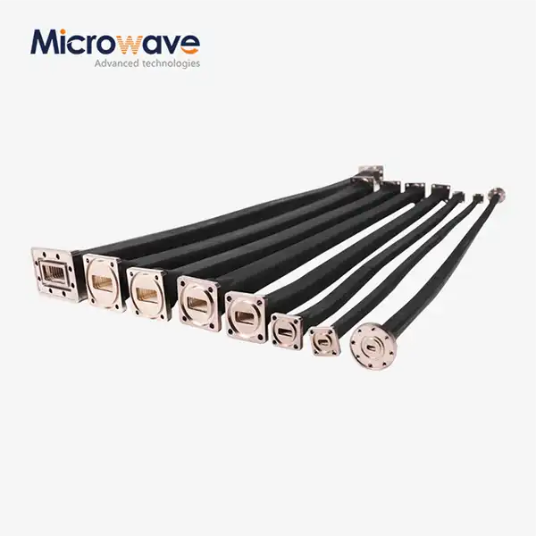
In addition to fixing polarisation, twists solve two practical routing problems: limited space in small payloads that are flown or sent by satellite; and structural reliability in places with a lot of vibration where flexible waveguides are not suitable.
Step Twist vs. Continuous Twist
ADM makes two versions that meet different engineering needs.
Step Twist uses internal impedance steps to spin the wave over a short distance. The small size is good for chassis plans that aren't very open. When compared to a continuous design, field concentrations at the steps may make it harder to handle peak power and lower the bandwidth that can be used.
Continuous (Tapered) Twist spreads the rotation out over the whole length of the part. This shape leads to fewer reflections, better VSWR, and more power handling. In exchange, the total size is longer, which is fine for most high-power radar and SATCOM assemblies.


Key Technical Specifications
Parameter | Value / Range |
Rotation Angle | 45°, 90°, 180° (custom angles available) |
VSWR | ≤ 1.10:1 (typically < 1.05:1 in narrow bands) |
Insertion Loss | < 0.1 dB (< 0.05 dB achievable in specific configurations) |
Frequency Coverage | Full waveguide band (WR-90 X-Band through WR-28 Ka-Band) |
Twist Type | Step Twist / Continuous (Tapered) Twist |
Material Options | Copper, Aluminum, Brass |
Surface Finish | Silver plating, Gold plating, Chromate conversion |
Flange Standard | MIL-DTL-85 |
Operating Environment | Standard; vacuum-compatible (specify at order) |
Materials and Surface Finish
The choice of material affects both the electrical performance and the weight of the Waveguide Twist.
Copper is best for high-power uses because it has the lowest skin-effect losses. Aluminium makes things lighter, which is important for payloads that are sent by air or space. Brass is a good general-purpose metal because it is easy to work with and doesn't rust.
Surface finish changes how well something works over time. Silver plating lowers insertion loss and lets more power flow through it. Test-grade parts always have gold finishing on them to stop oxidation. Chromate conversion layer on aluminium protects against corrosion in situations where signal loss is not very important.
Application Scenarios
Satellite Communication (SATCOM): There isn't a lot of room inside geostationary satellite packages. Orthogonal Mode Transducers (OMTs) are linked to diplexers by a product that rotates the signal path 90° to fit within strict volumetric envelopes without breaking impedance continuity.
When it comes to marine and airborne radar, high-power radar waveguide runs have to go around airframes or thick walls. The transmitter output flange is lined up with the antenna pedestal rotary joint with a twist. This keeps the right polarisation even when there is a lot of vibration.
In medical linear accelerators (LINAC), the product sends high-power radio frequency energy from the klystron to the structure that speeds things up. The twist makes sure that the rigid transmission lines stay in place and match impedance across the whole range of motion of the treatment gantry.
In lab bench setups, waveguide twists fix port orientation issues that happen when instruments and DUT fixtures are not lined up correctly, without adding any significant insertion loss.
Testing and Manufacturing
ADM tests parts in a 24-meter microwave darkroom that can switch between near-field and far-field measurements from 0.5 GHz to 110 GHz. This includes normal waveguide bands all the way up to millimeter-wave frequencies.
Flanges are made to meet the flatness and pressure sealing standards set by MIL-DTL-85. This means that the dimensions are always accurate across production batches.
Customization
The standard rotation angles of 45°, 90°, and 180° are enough for most integration situations. CNC machining with special tools can make angles that aren't normal, like 30° or 60°.
Vacuum-compatible versions are made from low-outgassing materials, like oxygen-free copper, and have vented flange joints to get rid of air pockets that get trapped. At the time of order, you can choose the type of flange, the mix of materials, and the plating that you want.
FAQ
Q: What is the difference between a Step Twist and a Continuous Twist?
A: A Step Twist rotates the wave over a short distance using impedance steps — compact but bandwidth-limited and with reduced peak power handling. A Continuous Twist distributes the rotation along a longer profile, producing better VSWR and higher power handling.
Q: Can a product operate in a vacuum environment?
A: Yes, provided it is manufactured with low-outgassing materials such as oxygen-free copper and correctly vented at the flange joints. Vacuum compatibility must be specified at the time of order.
Q: What rotation angles are available?
A: Standard angles are 45°, 90°, and 180°. Custom angles are achievable but require dedicated CNC tooling — contact ADM with your specific requirement.
Q: Does plating affect electrical performance?
A: Silver plating minimizes insertion loss and is preferred for high-power signal paths. Gold plating resists oxidation and is used in test-grade components. Chromate conversion on aluminum provides corrosion protection where insertion loss is a secondary concern.
Q: Which waveguide bands does ADM support?
A: ADM supports standard bands including WR-90 (X-Band), WR-28 (Ka-Band), and others across a measurement range of 0.5 GHz to 110 GHz.
Contact Us
To discuss your waveguide band, rotation angle, or custom Waveguide Twist configuration, contact ADM's engineering team at craig@admicrowave.com.