High Power Waveguide Power Dividers for Radar Systems: Design and Applications
It is very important for current radar devices to be able to send out high-power RF signals accurately and reliably. High power Waveguide Power Divider units are the most important part of sharing electromagnetic energy across multiple transmission routes while keeping signal integrity, phase coherence, and low insertion loss. These inactive parts make it possible for phased array radars, fire-control systems, and weather tracking radars to work at their best, even when they are under a lot of stress from the environment and heavy power loads. Waveguide power dividers are much better than their coaxial cousins at handling megawatts of pulsed energy and kilowatts of continuous wave power without breaking down or losing signal quality.
Understanding High Power Waveguide Power Dividers
The low-loss properties of hollow steel waveguide structures are used to make high power Waveguide Power Divider solutions that can split a single input signal into multiple output channels. These devices, which mostly work in the TE10 mode, are essential in situations where keeping the security of signals at frequencies above 8 GHz is a must.
Operating Principles and Core Functions
Waveguide power dividers work by using the way electromagnetic fields are spread out inside a carefully made metal hole. When an RF signal comes in through the input port, the divider's internal geometry—whether it's an E-plane tee, an H-plane tee, or a magic tee—splits the energy into waves with known amplitude and phase relationships. Since there are no insulating materials inside the waveguide, there are no losses like there are with PCB-based splitters. This makes these parts perfect for X-band (8.2–12.4 GHz) and S-band (2–4 GHz) radar uses. In monopulse radar systems, the magic tee design stands out as being very useful. It keeps the output ports very far apart (often more than 30 dB) and makes sum and difference patterns that are needed to figure out the goal angle. This feature lets radar systems tell the difference between things that are close together and improves tracking accuracy in busy electromagnetic environments that are busy.
Key Design Features for High Power Handling
Keeping track of high power levels requires paying close attention to how heat is lost, the materials used, and the accuracy of the shapes. Copper with a high conductivity that doesn't contain oxygen, and aluminum 6061-T6 are often used. They are often plated with silver or gold to stop rusting and reduce skin effect losses. Waveguides naturally get rid of heat better than coaxial wires because they have a larger cross-sectional area. This lowers the risk of multipactor discharge and arcing, which can severely damage or stop a system from working. To keep the field from concentrating, the inside surfaces are polished to very tight standards, and the joint points are made with smooth curves. In space uses or high-altitude radar platforms, dry nitrogen or SF6 gas can be used to pressurize dividers to make them Waveguide Power Dividers even stronger and keep them from breaking down in a vacuum.

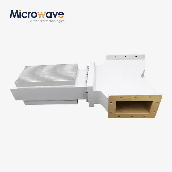
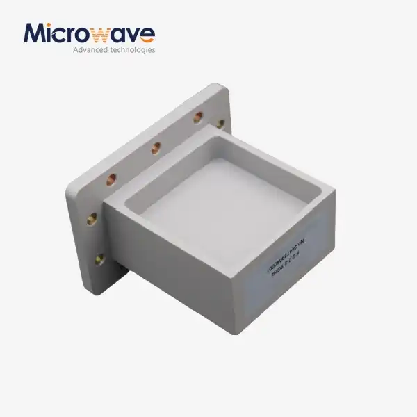
Common Configuration Types
E-plane dividers separate power by adding a septum that runs parallel to the electric field. They come in small sizes that make them easy to fit into tight array plans. H-plane dividers, on the other hand, split the waveguide along a plane that is not parallel to the magnetic field. They can handle more power, but they take up a little more space. Magic tees combine both E-plane and H-plane splits, making them the most flexible solution for situations that need to join signals and separate them in different directions. The insertion loss and separation properties of each setup are different. Magic tees may have insertion loss closer to 0.25 dB because their internal structure is more complicated than that of e-plane dividers, which usually have insertion loss below 0.15 dB. Which one to use depends on the needs of the whole system, like whether space-saving, power-holding, or isolation performance is more important.
Design Principles and Performance Optimization for Radar Systems
To get the best radar performance, you need to be very careful with the design and test it thoroughly. High power Waveguide Power Divider units need to correctly split signals and be able to handle the rough conditions of defense and aerospace settings.
Thermal Management and Material Selection
Even in waveguide systems, radar emitters often work at duty rates that make a lot of heat. Choosing the right material is the first step in managing heat well. Copper conducts electricity better than other metals, but it is heavier. Aluminum is better for airborne uses because it is lighter and easier to work with. However, it needs thicker walls or better plating to meet copper's performance. A lot of the time, heat sinks and cold plates are built into the supporting frame so that cooling can happen through conduction. It is not possible for convection to happen in vacuums, like satellite packages, so the divider needs to be directly attached to a radiator panel. Surface processes, like rhodium flash over silver, keep the metal from tarnishing without affecting its ability to carry electricity.
Phase and Amplitude Balance
For phased array radars to work, the phase and amplitude relationships between hundreds or thousands of transmitting elements must be exact. Even small changes—more than ±2 degrees in phase or ±0.2 dB in amplitude—can make beam guiding less accurate and limit the range of targets that can be found. To reach this balance, cutting-edge CNC machines and careful inspections during the manufacturing process using coordinate measuring tools are needed. We use our 24-meter microwave darkroom and antenna plane near and far field measuring recombination chamber at Advanced Microwave Technologies Co., Ltd. to make sure that the phase is consistent across the whole working span. The frequency range of our tests goes from 0.5 GHz to 110 GHz, so we can describe results in both normal and new radar bands.
Mitigating Multipaction and Electromagnetic Interference
When secondary electron emission cascades inside the waveguide, taking in power and making heat, this is called multipaction. This problem is especially bad at high altitudes or in space, where the air density isn't high enough to stop the buildup of electrons. Careful shape design, surface coatings, and gas pressurization are some ways to reduce the damage in a Waveguide Power Divider.
Both emitted and conducted electromagnetic interference can make nearby circuits less stable. It is very important to have good wiring, insulation, and flange closing. Using UG-387 and other related standards for hermetic seals makes sure that the job is done right every time and keeps the inside surfaces from getting contaminated or rusty.
Rigorous Testing and Validation Protocols
To check the performance, a vector network monitor measures S-parameters, namely S21 for insertion loss, S11 for return loss and VSWR, and S23 for port-to-port separation. VSWR stays below 1.20:1 across the whole waveguide bandwidth when high-quality dividers are used. High-power testing, which is usually done at or above the rated power, finds any possible temperature hot spots and makes sure the part can work continuously without breaking down. Our ISO 9001:2015 certification shows that we care about quality at all stages, from planning and making prototypes to mass production and shipping. For mission-critical uses, each divider is fully traceable and checked against strict acceptance criteria.
Comparison and Decision-Making: Choosing the Right Waveguide Power Divider
Finding the right power splitter means finding a balance between technical efficiency, physical limitations, and cost. Procurement engineers and radar system designers have to look at a lot of different factors to make sure that the Waveguide Power Divider they choose fits in perfectly and will last for a long time.
Power Capacity and Frequency Range
Coaxial splitters are small and cheap, but they can only handle a small amount of power (usually less than 100 watts constant) and have higher insertion loss at frequencies above 18 GHz. Waveguide power dividers, on the other hand, can handle steady power up to kilowatts and peak power up to megawatts. This makes them the only choice for high-power radar transmitters and directed energy uses. Range of frequencies is also important. Standard sizes are used to make waveguide dividers, such as WR-975 for L-band, WR-90 for X-band, WR-62 for Ku-band, and so on. The physical limit frequency tells us what size covers what spread. If you choose the right waveguide size, the splitter will work in its best range, preventing unwanted modes and keeping the VSWR low.
Isolation and Insertion Loss
In multi-channel radar systems, it is very important that the output ports are well isolated so that mirrored signals from one channel don't throw off signals from another channel. In this case, magic tees work best because they offer separation of more than 30 dB, while simple T-junctions may only offer 15–20 dB. Insertion loss has a direct effect on how well a system works. Less loss means that more broadcast power gets to the receiver, and it can receive signals more clearly. Waveguide dividers always work better than flat options; well-designed units usually have insertion losses below 0.2 dB.
Physical Footprint and Integration
Waveguide dividers are bigger than coaxial or microstrip options, but their ability to protect against damage and make the system easier to integrate makes up for it. Flanges are made to meet industry standards, which makes them interchangeable and easy to put together. Custom designs can include fixing features, cooling ducts, and adjustment pins that are made to fit the limitations of a certain platform.
Cost-Effectiveness and Total Cost of Ownership
The initial cost of buying something is only one factor. Total cost of ownership is affected by long-term dependability, ease of upkeep, and the ability to update. High-quality divisions last longer and don't need to be replaced as often, which makes up for the higher initial cost. Even though they are more expensive at first, custom OEM solutions often offer better performance and integration, making the system simpler and more ready for use.
Procurement Guide for High Power Waveguide Power Dividers
To find good Waveguide Power Divider units, you need to plan ahead and think about what the vendors can do, how long the wait times are, and what approval standards are needed. Early interaction with manufacturers who offer technical help, customization, and fast prototyping is good for procurement teams.
Identifying Trustworthy Suppliers and Manufacturers
Suppliers with a good reputation have a track record in the defense, aircraft, and telecoms industries and are certified by ISO 9001. Full datasheets, S-parameter files, and engineering models should be given by vendors. It is important to be clear about lead times, minimum order amounts, and price structures. We at Advanced Microwave Technologies Co., Ltd. have been creating and making precise RF parts for more than 20 years. The most up-to-date test equipment, up to 110 GHz, is in our labs. All of our Waveguide Power Divider goods are RoHS compliant and ISO 9001:2015 approved. We provide waveguide assemblies, coaxial components, and special OEM solutions to defense companies, aircraft engineers, and satellite communication providers all over the world.

Custom Manufacturing and OEM Options
Components that are available off the shelf might not work with modern radar devices. Custom designs let you get the best frequency range, power handling, port layout, and mechanical connections. Rapid prototyping shortens the time it takes to build something, so you can test its performance before going to full-scale production. We offer custom OEM services that include making prototypes, making changes to designs, and mass production. Our engineering team works closely with customers to make sure that requirements are clear, that performance is tested, and that the products work well with other systems.
Pricing, Lead Times, and Bulk Ordering
Standard waveguide dividers usually have lead times of 4 to 8 weeks. Custom versions, on the other hand, can take 10 to 16 weeks, based on how complicated they are. Planning ahead and evaluating samples early on lowers risk and keeps projects on track. There are often bulk discounts for large orders, but buying teams should weigh the cost savings against the costs of keeping inventory and the need to be able to make changes to the design. Our strong supply chain and efficient production methods allow us to offer competitive prices without lowering the quality of our products. We work openly with clients to set reasonable deadlines and give them regular information during the production process.
Evaluating Vendor Credibility
Getting certifications like ISO 9001, ISO 14001, and ISO 45001 shows that you care about quality, the environment, and safety at work. Technical support, such as help with installation, fixing problems, and service after the sale, is also very important. Customer reviews, case studies, and references can tell you a lot about how reliable and responsive a seller is. Our dedication to perfection goes beyond just delivering products. To make sure our customers are happy in the long term, we offer detailed expert help, quick responses to questions, and ongoing support. Our ISO 14001:2015 and ISO 45001:2018 standards show that we care about both the health and safety of our employees and the environment.
Conclusion
High power Waveguide Power Divider units are essential parts of modern radar systems because they can handle a lot of power, have low insertion loss, and provide excellent separation. For the best performance in the toughest situations, pay close attention to temperature management, phase balance, and material choice. Partnering with experienced makers who offer customization, thorough testing, and full support is good for procurement teams. As radar technology improves, waveguide dividers will also change, adding new materials and smart integration features to meet the needs of the next generation of defense, military, and communications systems.
FAQ
What distinguishes a magic tee from a simple T-junction waveguide power divider?
A simple T-junction divides power but only blocks 15–20 dB of noise between output ports. In a magic tee, there is a fourth port that offers great separation (often more than 30 dB) and the ability to make both sum and difference signals. Because of this, magic tees are perfect for monopulse radar systems that need to accurately track angles and tell the difference between targets.
Can waveguide power dividers function as combiners?
It's true that Waveguide Power Divider units work both ways and can also be used to mix power. It is very important that the timing and amplitude of the raw data match when combining them. If the inputs aren't consistent, energy will be lost in the isolation port or reflected back to the source, which could lead to warming and less efficiency.
How do environmental factors affect waveguide power divider performance?
Changes in temperature, humidity, and mechanical stress can all affect how well something works. The internal measurements change because of thermal expansion, which changes phase balance and VSWR. These effects can be lessened by using the right materials, closing them properly, and making sure they are stable mechanically. Space-rated divisions are made not to break down when exposed to radiation, vacuums, and changes in temperature.
What are the typical lead times for custom waveguide power divider designs?
Most standard setups are sent out between 4 and 8 weeks after ordering. Depending on how complicated they are and how many tests they need, custom designs can take 10 to 16 weeks. Getting involved with makers early on and carefully going over the specifications speeds up the process. Before committing to full production runs, prototype builds let you test how well they work.
Partner with ADM for High-Performance Waveguide Power Divider Solutions
Advanced Microwave Technologies Co., Ltd. can help you build a radar system by providing you with custom Waveguide Power Divider units and full OEM services. We make parts that meet the strict requirements of defense, aircraft, and satellite communication uses. We have been making parts for over 20 years and are ISO 9001:2015 certified. Our state-of-the-art 24-meter microwave studio and test capabilities up to 110 GHz make sure that every product works perfectly and is reliable. Our experienced engineering team can help you with fast prototyping, technical support, and low prices, no matter if you need standard setups or fully customized designs. Email craig@admicrowave.com to talk to ADM about your waveguide power divider needs and find out how our quality, freedom, and global logistics can help your project succeed faster.
References
1. Pozar, David M. Microwave Engineering, 4th Edition. Wiley, 2011.
2. Collin, Robert E. Foundations for Microwave Engineering, 2nd Edition. Wiley-IEEE Press, 2001.
3. Bahl, Inder and Prakash Bhartia. Microwave Solid State Circuit Design, 2nd Edition. Wiley-Interscience, 2003.
4. Montgomery, C.G., R.H. Dicke, and E.M. Purcell. Principles of Microwave Circuits. IET, 1987.
5. Skolnik, Merrill I. Radar Handbook, 3rd Edition. McGraw-Hill, 2008.
6. Rizzi, Peter A. Microwave Engineering: Passive Circuits. Prentice Hall, 1988.