





Elliptical Microwave Waveguides: Attenuation Curves Decoded
To understand elliptical microwave waveguides, you need to know more than just the basics of how RF signals work. These specialized components utilize a corrugated elliptical cross-section to guide electromagnetic energy with remarkable efficiency, combining the low-loss traits of standard fixed waveguides with unprecedented installation freedom. Attenuation curves show how signal strength decreases across frequency bands. This has a direct effect on how well systems work in telecom towers, satellite uplinks, and radar installations. We make elliptical microwave waveguides with UV-resistant polyethylene jackets and corrugated copper construction at Advanced Microwave Technologies Co., Ltd. These are designed to deliver better performance while reducing deployment complexity in mission-critical applications ranging from 3 GHz to 40 GHz.
Understanding Elliptical Microwave Waveguides and Their Attenuation Characteristics
Elliptical microwave waveguides are a sophisticated step forward in the technology used to send radio waves. Unlike rigid rectangular structures requiring numerous flanges and elbows, these flexible assemblies maintain the electromagnetic advantages of waveguide technology while accommodating complex installation pathways found in tower environments and earth station facilities.
The Fundamentals of Elliptical Geometry and Signal Propagation
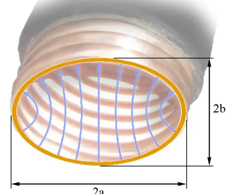
The elliptical cross-section mostly works in the TE₁₁ mode, where the major and minor planes of the shape line up with the wave polarization. The waveguide can bend in two different directions with this configuration: the E-plane bends along the minor axis and has tighter radius limits, while the H-plane bends against the major axis and needs to meet stricter minimum bend limits. Material conductivity is a key factor in how well reduction works. Our copper construction makes sure that the surface current flows smoothly, reducing the amount of resistive loss that rises with frequency.
Critical Factors Shaping Attenuation Curves
How attenuation changes across the operational bandwidth is controlled by a number of parameters that are all linked to each other. Higher frequencies have a lot of conductor losses because of the skin effect concentration near the waveguide surface. While the corrugated structure makes the mechanical flexibility possible, it also causes periodic changes in the impedance that must be carefully managed during production. Changes in temperature have an effect on both the physical dimensions and the electrical properties. The corrugated structure acts like an accordion when temperatures rise and fall, absorbing mechanical stress without breaking. When designs are filled with air, dielectric losses aren't a big deal, but they become a big problem when moisture gets into the waveguide system. Pressurizing with dry nitrogen stops condensation, which keeps the dielectric qualities stable and stops voltage breakdown during high-power gearbox operation.
How Attenuation Curves Guide System Design Decisions?
When engineers figure out link costs and power needs, they use attenuation curves as a guide. It is common for specs to list 2.5 dB per 100 meters at 10 GHz and 5.8 dB per 100 meters at 26 GHz. In long-haul applications, these values have a direct effect on the distance between repeaters and determine the lengths of cables that can be run between ground equipment and antenna feeds. When procurement specialists understand frequency-dependent attenuation, they can choose waveguide sizes that meet mechanical installation requirements while also maximizing electrical efficiency.
Comparative Performance Analysis: Elliptical vs. Other Microwave Waveguides
Selecting appropriate transmission line technology requires a systematic comparison of electrical performance, mechanical properties, and total cost of ownership across different platform options available in the marketplace.
Elliptical Waveguides Versus Coaxial Cable Solutions
When working at frequencies above 3 GHz, coaxial lines lose a lot of signal, which means they can't be used for tower runs longer than 50 meters. A 1-5/8" coaxial cable might lose 8 dB per 100 meters at 10 GHz, but an elliptical microwave waveguide achieves only 2.5 dB. This is a threefold improvement that directly leads to higher system gain and fewer amplifiers being needed. Another big advantage is the ability to handle power. Coaxial dielectric materials can only handle a few hundred watts of continuous power, but air-dielectric waveguide assemblies can handle kilowatt-level transmission without worrying about voltage breakdown or thermal degradation.
Comparison with Rigid Rectangular Waveguide Systems
Traditional rectangular waveguides have great electrical performance, with tightly controlled dimensions and low loss. However, they are very hard to install because every direction change needs precision-machined elbows and flange connections, each of which introduces mechanical alignment issues and potential reflection points. The cumulative effect of multiple junctions degrades overall VSWR performance and significantly extends installation times. Elliptical microwave waveguides get rid of 70–80% of these connection points through continuous flexible runs that navigate tower structures without rigid geometry constraints. Our measurements show VSWR is usually below 1.15:1 across the operating band, which is comparable to rigid installations while delivering a vastly improved installation efficiency.
Evaluating Circular Corrugated and Ridge Waveguide Alternatives
It is possible for circular corrugated waveguides to bend in any direction, but they don't have the polarization control benefits that come with elliptical geometry. Ridge waveguides allow for longer, lower frequency operation in smaller packages, but they have higher attenuation per unit length compared to standard designs. For most telecom and radar applications, the elliptical shape is the best balance between mechanical flexibility, electrical performance, and manufacturing ease. This is why it is widely used in microwave backhaul networks around the world.
Design Principles and Simulation of Elliptical Microwave Waveguides
The best performance of elliptical microwave waveguides comes from strict engineering methods that combine electromagnetic modeling, material science, and precision manufacturing skills gained over many years of specialized production experience.
Core Design Strategies for Minimizing Attenuation
Geometry optimization starts with carefully choosing the major and minor axis dimensions that set the cutoff frequency and single-mode operational bandwidth. Our design teams use electromagnetic simulation platforms to model field distributions and predict attenuation characteristics before making prototypes. The quality of the surface finish has a direct effect on conductor losses through its effect on effective conductivity at RF frequencies. We keep tight control over corrugation-forming processes.
Simulation Tools and Predictive Modeling Capabilities
Advanced simulation platforms create accurate attenuation curves across the entire frequency range, taking into account conductor losses, geometric tolerances, and higher-order mode coupling effects. These predictive models let us find the best corrugation pitch, depth, and profile before we spend money on tooling. Thermal analysis models show how heat dissipates under high-power conditions, making sure that temperature rises stay within safe operational limits. Mechanical stress simulations make sure that the bend radius specifications keep the structure's integrity through installation and operational loading cycles. The correlation between simulation results and measured performance in our ISO 9001:2008-certified laboratories verifies design methods and gives customers high confidence that their needs are met.
Manufacturing Considerations Affecting Procurement Decisions
Manufacturing tolerances have a direct effect on how consistently the electrical performance of elliptical microwave waveguides is across production volumes. We keep dimensional control within micrometers on critical parameters that affect impedance and cutoff frequency. Surface treatment processes make sure that the conductivity is optimal while also providing corrosion resistance for long-term environmental exposure. The UV-resistant black polyethylene jacket goes through high-voltage spark testing to confirm dielectric integrity before assembly completion. These quality control measures, along with comprehensive swept VSWR and attenuation measurements using vector network analyzers calibrated to 110 GHz, give procurement teams confidence in the reliability of the component. Our rapid prototyping capabilities support custom designs with shortened development timelines, meeting the unique needs of defense, aerospace, and research applications.
Real-World Applications and Advantages of Elliptical Microwave Waveguides
Deployment in various industrial sectors shows measurable performance benefits that support choosing technologies and investing in them in environments with competitive procurement.
Telecommunications Infrastructure and Microwave Backhaul Networks
Microwave links are used by cellular network operators to send large amounts of data between cell sites and core network facilities. Elliptical microwave waveguides connect base transceiver stations to parabolic antennas on towers, working across 6 GHz to 38 GHz frequency bands that support multi-gigabit throughput requirements. The ability to run continuously lowers passive intermodulation products, which lower signal quality in dense urban environments. Lower attenuation compared to coaxial alternatives increases link distances, lowering the number of repeater sites needed across regional networks. Installation time savings directly affect tower crew costs and speed up network deployment schedules during capacity expansion projects.
Satellite Ground Station Applications
Earth station facilities that send signals to geostationary satellites need waveguide assemblies that can handle kilowatt-level power from high-power amplifiers. Our elliptical microwave waveguide products have the power-handling capacity and low-loss characteristics needed to maximize effective isotropic radiated power. The flexible design allows for thermal expansion between indoor transmitter locations and outdoor antenna pedestals without introducing mechanical stress concentrations. Pressurization systems maintain the quality of the internal atmosphere, stopping moisture-induced attenuation increases that compromise uplink margins. Using these performance characteristics is important for ground station operators in commercial teleport facilities and military satellite communication complexes to stay connected.
Radar Systems and Defense Electronics
Flexible elliptical microwave waveguide technology makes it possible for tactical radar installations to be set up quickly. Mobile radar systems on vehicles are subject to vibration and thermal cycling that would damage rigid waveguide assemblies. The corrugated structure absorbs mechanical stresses while maintaining electrical stability in demanding operational environments. Defense contractors that put radar subsystems into planes, ships, and vehicles on the ground need customized waveguide assemblies with specific flange configurations, length tolerances, and environmental sealing specifications. Our OEM services offer custom solutions with full technical support from design consultation to installation guidance, ensuring seamless integration into complex weapon system architectures.
Conclusion
In telecommunications, satellite, radar, and aerospace applications, elliptical microwave waveguide technology improves attenuation performance, installation efficiency, and operational reliability. Knowing about attenuation curves helps you make smart purchasing decisions that maximize system performance while keeping the total cost of ownership low. Advanced Microwave Technologies Co., Ltd. has over twenty years of experience manufacturing products and is ISO 9001:2008 certified for quality systems. Our corrugated copper construction with UV-resistant jacketing is a cost-effective alternative to more expensive competitors without sacrificing electrical or mechanical performance. Strategic partnerships with manufacturers that offer customization options, responsive technical support, and global logistics infrastructure strengthen the supply chain while speeding up deployment schedules.
FAQ
1. What differentiates E-plane and H-plane bending specifications?
E-plane bending happens along the minor axis of the elliptical cross-section, which allows for smaller bend radii because of the way the geometry is set up. H-plane bending against the major axis needs larger minimum radii to avoid corrugation deformation, which lowers electrical performance. Installers must carefully follow the manufacturer's instructions for each plane to keep the waveguide assembly from being permanently damaged by too much stress.
2. Why does pressurization matter in waveguide installations?
When you pressurise elliptical microwave waveguides with dry air or nitrogen, moisture doesn't build up inside the waveguide, which would weaken the signal and cause internal corrosion. Positive pressure also makes the dielectric stronger, which stops voltage breakdown during high-power gearboxes. Pressure monitoring systems let operators know when the jacket breaks and needs to be fixed before performance goes down.
3. Can field termination support custom installation requirements?
Using special flaring tools and connector hardware to connect elliptical microwave waveguides in the field is possible. To do it right, you need to clean up any metal debris, flare the corrugations precisely, and make sure the dimensions are correct for low VSWR connections. Factory-terminated assemblies are better for many installations because they guarantee consistent quality, but field termination gives you the freedom to deal with unplanned site conditions during complex installations.
Partner with ADM for Superior Elliptical Microwave Waveguide Solutions
Advanced Microwave Technologies Co., Ltd is ready to help you with your next RF infrastructure project by providing high-quality elliptical microwave waveguides that are backed by ISO certification and a wealth of technical knowledge. Our global supply chain ensures competitive pricing without lowering the quality standards needed by the aerospace, defence, and telecommunications sectors. Whether you need catalogue products or fully customised assemblies made to meet the specific needs of your system, our experienced engineering team is here to help you from the initial design phase through installation completion. Email craig@admicrowave.com to talk about your needs with a reliable elliptical microwave waveguides supplier. We offer rapid prototyping, volume discounts, and after-sales support that make your supply chain more reliable and shorten project timelines in tough procurement environments.
References
1. Clarricoats, P. J. B., & Saha, P. K. (1971). "Propagation and Radiation Behavior of Corrugated Feeds: Part 1—Corrugated Waveguide Feed." Proceedings of the Institution of Electrical Engineers, 118(9), 1167-1176.
2. Marcuvitz, N. (1986). "Waveguide Handbook." Institution of Engineering and Technology Electromagnetic Waves Series, Dover Publications.
3. Collin, R. E. (1991). "Field Theory of Guided Waves: Second Edition." IEEE Press Series on Electromagnetic Wave Theory, Wiley-IEEE Press.
4. Orfanidis, S. J. (2016). "Electromagnetic Waves and Antennas." Rutgers University Department of Electrical and Computer Engineering Technical Publication.
5. Saad, T. S. (1985). "Microwave Engineers' Handbook: Volume 1." Artech House Microwave Library, Artech House Publishers.
6. Pozar, D. M. (2011). "Microwave Engineering: Fourth Edition." John Wiley & Sons, Hoboken, New Jersey.
YOU MAY LIKE
 VIEW MOREWaveguide Power Divider
 VIEW MOREHigh Power Waveguide Differential Phase Shift Isolator
 VIEW MOREWG Pressure Window
 VIEW MOREWaveguide Single Channel Rotary Joint
 VIEW MOREWaveguide Tube
 VIEW MOREDouble Ridge Waveguide Rotary Joint
 VIEW MORECoaxial Bandpass Filter
 VIEW MORELow Side Lobe Diagonal Linear Polarization Horn Antenna
