





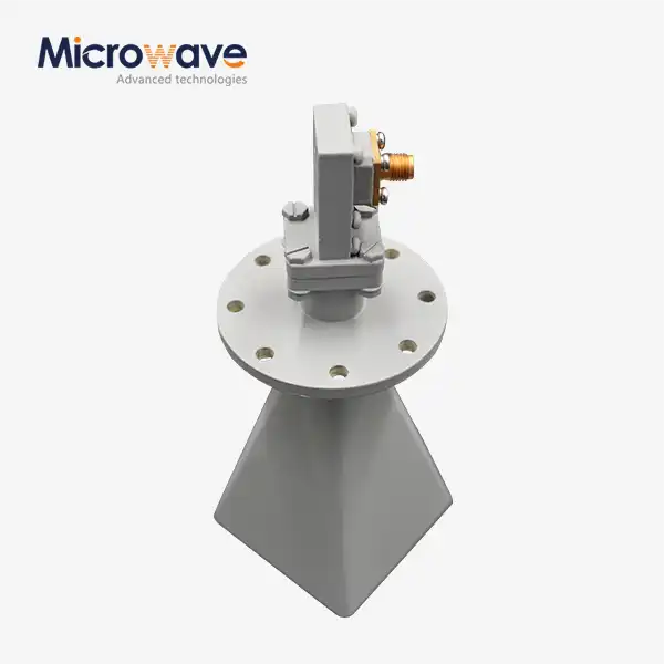
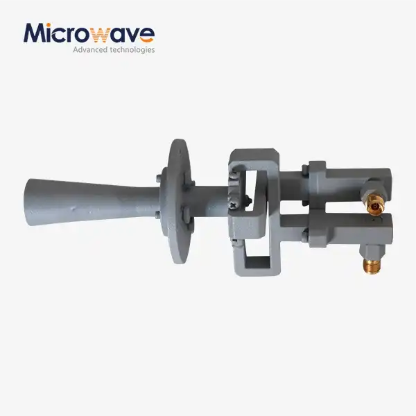
Low Side Lobe Diagonal Linear Polarization Horn Antenna
Low Side Lobe Diagonal Linear Polarization Horn Antenna
The Low Side Lobe Diagonal Linear Polarization Horn Antenna from Advanced Microwave (ADM) covers 2,000 to 60,000 MHz across standard waveguide bands and delivers gain options from 10 to 25 dB. It is different from other pyramidal horns because it has a square aperture excited in diagonal mode, which combines TE10 and TE01 modes to make a rotationally symmetric beam with side lobe levels usually below -25 dB to -30 dB in the E- and H-planes. The 24 m anechoic room at ADM, which works from 0.5 GHz to 110 GHz, checks each unit.
How the Low Side Lobe Diagonal Linear Polarization Horn Antenna Design Solves a Fundamental Horn Limitation?
The E-plane and H-plane beamwidths of standard pyramidal horns are not the same. This unevenness leads to spillover losses, uneven reflector illumination, and higher measurement uncertainty in test settings that need to be careful.
When the orientation is diagonal, the electric field lines up with a synthesised orthogonal mode distribution. This makes the aperture field naturally taper. The E-plane and H-plane beamwidths are almost the same, which is something that uniform-aperture horns can't do just by looking at geometry.
This design also provides Cross-Polarization Discrimination (XPD) greater than 35 dB, which is important in places with a lot of spectral information and in precision radiometric sets where polarisation leakage directly affects the accuracy of measurements.
Note on design: Low side lobe performance only works for the E-plane and H-plane. When the observation angle moves away from these two main planes, side lobe suppression gets worse. This is a basic property of the diagonal horn architecture that should be taken into account when planning the layout of the system.
Key Technical Specifications
Parameter | Specification |
Frequency Range | 2,000 – 60,000 MHz |
Gain Range | 10 – 25 dB |
Side Lobe Level (SLL) | < -25 dB to -30 dB (E & H planes) |
Cross-Polarization Discrimination (XPD) | > 35 dB |
VSWR | < 1.2:1 or 1.3:1 (operating bandwidth) |
Beam Symmetry | E-plane ≈ H-plane (axis-symmetric) |
Waveguide Compatibility | Standard bands (e.g., WR-15, WR-28) |
Material | Precision-milled aluminum or copper |
Surface Finish | Silver or gold plating |
Materials and Construction
Each Low Side Lobe Diagonal Linear Polarization Horn Antenna is precision-milled from solid aluminum or copper. At Ka-band (26.5–40 GHz), V-band (50–75 GHz), and W-band frequencies, the surface finish has a direct effect on ohmic loss. To reduce resistive losses and stop long-term oxidation, silver or gold plating is used.
Not a single insulation piece is inside the horn. This means that the design can handle a lot of continuous wave (CW) power. To keep the voltage from dropping at the waveguide contact in very high-power situations, it is suggested that the feed flange be pressurised.
A Coordinate Measuring Machine (CMM) is used to check the throat and opening sizes to within microns of accuracy. Small errors at these key points affect the purity of the mode and raise the side lobe levels, so during production, dimensional accuracy is seen as a must.
Quality Control Process
ADM applies a multi-stage inspection process before any unit ships. Each stage targets a specific failure mode:
· Far-Field Radiation Pattern Verification — Conducted inside ADM's 24 m anechoic chamber. Confirms SLL meets the specified threshold and validates main beam symmetry across the frequency band.
· Cross-Polarization Isolation Test — Verifies that diagonal mode excitation is correctly aligned to maintain XPD values above specification.
· VSWR and Return Loss Measurement — Performed with a Vector Network Analyzer (VNA) across the full specified band to confirm impedance matching.
· CMM Dimensional Inspection — Checks throat and aperture geometry at micron-level precision.
· Surface Finish and Plating Adhesion Check — Addresses passive intermodulation (PIM) risk and long-term oxidation.
Each unit ships with a test report covering measured Gain vs. Frequency curves, VSWR plots, and normalized radiation patterns at low, mid, and high frequency points within the band.
Typical Application Scenarios
Compact Antenna Test Range (CATR) Feeds
In aerospace and defense testing, this antenna is used as a feed for collimating reflectors. Its low side lobe characteristic prevents stray radiation from reaching chamber walls or reflector edges, reducing ripple and measurement uncertainty in the Quiet Zone.
Satellite Communication Reflector Systems
Equal E/H beamwidths maximize aperture efficiency when illuminating parabolic dishes. Suppressed side lobes reduce adjacent satellite interference — a key constraint in crowded geostationary arc environments.
Precision Radiometry and Remote Sensing
For atmospheric and environmental monitoring, suppressed side lobes prevent unwanted energy contributions from ground or surrounding hardware from entering the receive path, which directly improves the G/T (Gain-to-Noise Temperature) ratio.
Customization and Configuration Options
ADM supports gain selection from 10 to 25 dB across standard waveguide frequency bands within the 2–60 GHz range for the Low Side Lobe Diagonal Linear Polarization Horn Antenna. Contact ADM's engineering team to discuss frequency extension, flange interface requirements, or integration into CATR systems, satellite terminals, and radiometric receivers.
FAQ
Q: How does the diagonal horn achieve lower side lobes than a standard pyramidal horn?
A: The diagonal orientation combines two orthogonal modes (TE10 and TE01), making a tapered aperture field distribution that reduces side lobes and balances beamwidths in the E and H planes. Standard horns depend on an even distribution of apertures, which can't do the same job.
Q: What range of frequencies are there?
A: The standard series works with waveguide bands such as Ka-band (26.5–40 GHz) and V-band (50–75 GHz) and can handle frequencies from 2,000 to 60,000 MHz.
Q: What about high CW power? Can these antennas handle it?
A: High CW power levels can be handled by constructions made of solid aluminium or copper that don't have any dielectric parts. For very high-power uses, it is suggested that the feed flange be pressurised to avoid breakdown at the waveguide interface.
Q: Do you know why beam symmetry is important for mirror feed applications?
A: Different E/H beamwidths light up the reflector in different ways, which leads to efficiency loss and spillover. A symmetric pattern makes the most of the reflector's gain and cuts down on signal energy that is wasted.
Q: Does each unit come with a test report?
A: Yes. The test report that comes with each unit shows the recorded Gain vs. Frequency, VSWR plots, and normalised radiation patterns at several frequency points across the band.
Q: Do the side lobes stay low no matter what angle you look at them from?
A: No, the E-plane and H-plane are the only ones that have low side lobe performance. When the observation angle moves away from these main lines, performance goes down. This is a basic property of the diagonal horn design.
Contact Us
To discuss specifications, gain options, or frequency requirements for the Low Side Lobe Diagonal Linear Polarization Horn Antenna, contact ADM at craig@admicrowave.com.
YOU MAY LIKE
 VIEW MORESlotted Waveguide Array Antenna
 VIEW MOREParabolic Antenna
 VIEW MOREFeed Fired Lens Antenna
 VIEW MOREMini Wideband Double-ridged Horn Antenna
 VIEW MOREOpen Boundary Dual Linear Polarization Four Ridged Horn Antenna
 VIEW MORELadder Membrane Conical Dual circular Polarization Horn Antenna
 VIEW MOREDual Linear Broadband Circular Polarization Horn Antenna
 VIEW MOREConical Linear Polarization Horn Antenna
