Broadwall Double Ridge Waveguide Coupler Directivity Explained
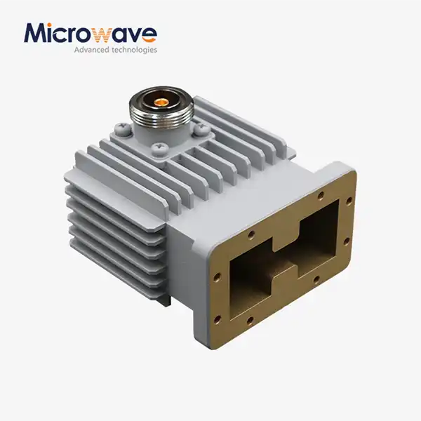
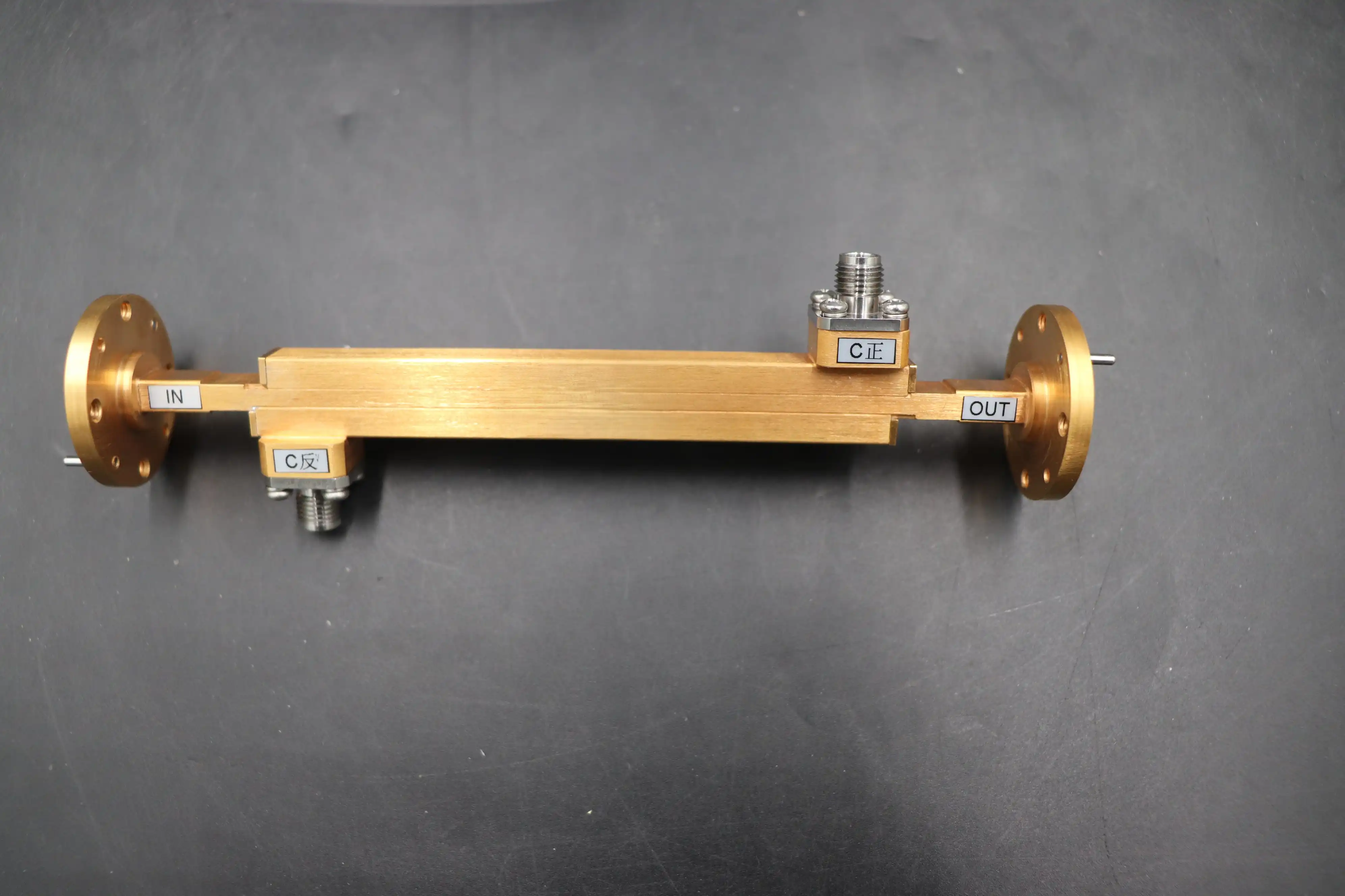
When it comes to a broadwall double-ridge waveguide coupler, directivity means that the part can tell the difference between forward and reflected signals. This makes sure that measured power only comes from the desired transmission direction. This passive microwave device collects RF signals over very large frequency ranges. It solves a problem that has been around for a long time in microwave engineering: getting multi-octave bandwidth without signal separation being compromised. The double-ridged shape capacitively loads the waveguide center, making it more operationally broad than rectangular designs while keeping high directed discrimination, which is usually more than 15-20 dB across the whole spectrum.
Understanding Broadwall Double Ridge Waveguide Coupler Directivity
The Physics Behind Directional Coupling
The coupler's ability to separate forward power from backward reflections is based on its directivity. In broadwall double-ridge waveguide coupler designs, the ridges create capacitive loading that changes the way waves travel in a fundamental way. The double-ridged structure drops the TE10 cutoff frequency while raising the bar for higher-order modes. This is different from regular rectangular waveguides, which can only handle about 40% fractional bandwidth. This change makes the single-mode bandwidth usable up to 200–300% wider, which can handle frequency ratios of up to 3.6:1 in designs that follow the WRD650 or WRD750 standards.
Coupler holes are placed along the bigger waveguide wall, which is where the electric field strength is strongest in the broad-wall design. Multi-hole arrays that are carefully designed and often follow Tchebyscheff distribution patterns sample electromagnetic energy consistently across frequencies that span an octave. The directivity performance is based on the phase relationships between linked holes. For example, a quarter-wavelength spacing at the design center frequencies causes damaging interference for waves traveling backwards while combining forward signals in a positive way.
Electromagnetic Properties Influencing Directivity
The choice of material has a direct effect on the stability of directivity. Aluminum 6061-T6 and copper alloys of high quality reduce ohmic losses that hurt signal isolation. Surface treatments like silver plating or chromate conversion coatings lower resistive losses to less than 0.1 dB per coupling section. This keeps the directivity specifications the same, even when there is a lot of power going through it. These materials set up electromagnetic boundary conditions that make field patterns predictable, which is important for reliable directional performance.
Matching the impedance over a wide operational bandwidth is hard in its own way. The ridges slowly change the characteristic resistance, which keeps the VSWR below 1.4:1 across the whole frequency range. This environment with controlled impedance stops standing waves that would mess up measurements of directivity otherwise. Our engineering team has seen that even small changes in resistance at ridge transitions can lower directivity by 3–5 dB at band edges. This shows how precise these designs need to be.
Technical Specifications and Design Parameters Affecting Directivity
Critical Dimensional Tolerances
The most important factor in coupler design is the ridge gap width. Small differences, like a few microns, can change the cutoff frequencies and the phase relationships that set the directionality. Coordinate measuring machines are used by Advanced Microwave Technologies Co., Ltd. to make sure that the dimensions of the ridges are within ±0.001 inches of each other. This makes sure that the directivity specifications stay the same across production runs.
The coupling aperture geometry, which includes the hole diameter, wall thickness, and spacing, needs to be optimized across the whole target bandwidth at the same time. When apertures get smaller, they weaken the coupling but make directivity better at high frequencies. When apertures get bigger, they strengthen the coupling but make directivity worse. To meet all of these different needs, we need to use complex electromagnetic modeling that is checked against recorded data from our 24 m microwave darkroom facility.
Frequency-Dependent Performance Characteristics
Because coupling mechanisms change with frequency, directivity performance changes across the operational bandwidth. Directivity usually peaks above 25 dB at lower frequencies, where the electrical distance between connection holes is getting close to the best quarter-wavelength spacing. As the frequency gets closer to the edges of the band, phase cancellation gets less perfect, which lowers directivity to minimum levels around 15 dB. This behavior is built into wideband systems and is a managed trade-off for having very good bandwidth coverage.
We have tested systems from 0.5 GHz to 110 GHz and found that coupling flatness, which is the change in nominal coupling value across frequency, is directly related to directivity stability. Designs that keep coupling changes to within ±1.0 dB show more stable directivity curves. During the construction phase, this relationship helps us choose the locations of the coupling holes and the shapes of the ridge taper in a broadwall double-ridge waveguide coupler.
Simulation and Fabrication Integration
Electromagnetic simulation tools, such as HFSS and CST Microwave Studio, let you model the performance of directivity before you actually make the part. By solving Maxwell's equations in three-dimensional coupler shapes, these tools show how fields are distributed and how S-parameters respond. We regularly check the results of our simulations against measurements from the vector network analyzer. This helps us improve our modeling methods so that we can get accuracy for directivity predictions within 0.5 dB.
Precision CNC machining turns designs that are optimized into parts that can be used. Multi-axis machining centers keep the necessary dimensional tolerances for directivity performance, and automatic checking systems make sure that important features meet the requirements. At millimeter-wave frequencies, the quality of the surface finish affects how current flows, so we require internal coupling surfaces to have a surface roughness below 32 micro-inches RMS. These manufacturing rules make sure that production units work as well as they were simulated to do.
Comparing Broadwall Double Ridge Waveguide Couplers to Alternative Solutions
Performance Benchmarking Against Standard Waveguides
In their narrow bandwidth, traditional rectangular waveguide couplers provide great directivity, often reaching 30 dB isolation across 20 to 30 percent fractional bandwidths. To cover multi-octave frequency ranges, however, you have to switch between different waveguide sizes, which adds to the complexity of the system and could lead to calibration errors. The broadwall double-ridge waveguide coupler method combines this functionality into a single part, giving up a small amount of directivity (15–20 dB) in exchange for a bandwidth increase of over 100%.
Comparing insertion loss shows another benefit. Normal waveguide couplers lose about 0.2 to 0.3 dB per section. Double ridge types work just as well, even though they have a wider frequency. This efficiency comes from the waveguide's naturally low-loss transmission mode, which is better than cable options at microwave frequencies.
Microstrip and Coaxial Coupler Alternatives
Microstrip directional couplers provide compact form factors and ease of integration with planar circuits. Their directivity is usually between 12 and 18 dB at narrower bandwidths, and their performance quickly drops above 20% fractional bandwidth. The broadwall double-ridge architecture is the best choice for applications that need directivity above 15 dB across multiple octaves.
Coaxial couplers are used in situations where space is more important than bandwidth. Modern coaxial systems can work at frequencies between 6 and 18 GHz, but they can't handle as much power as broadwall double-ridge waveguide coupler structures can. A double-ridge coupler with the same bandwidth rating can handle continuous power up to kilowatts, which makes it essential for high-power radar testing and transmitter monitoring tasks where coaxial parts would fail.
Market Landscape and Leading Solutions
Defense and aerospace are where the market leaders in broadwall waveguide technology are focusing their efforts right now. Electronic warfare systems have become more interested in vendors who offer WRD-series parts with defined directivity above 15 dB across their operating bands. Tests from outside sources in the industry show that couplers that keep the coupling flatness within ±1.0 dB give the most stable directivity performance in real-world settings.
Applications and Benefits of Broadwall Double Ridge Waveguide Couplers in Industry
Defense and Aerospace Systems
Airborne electronic warfare suites demand lightweight, wideband components capable of monitoring transmitter output across threat frequency ranges spanning 6-18 GHz or wider. When compared to multi-coupler approaches, broadwall double-ridge waveguide couplers cut system weight by 40–60% because they don't need as many narrowband components. Power monitoring accuracy stays within ±0.5 dB thanks to the high directivity. This is true even in tactical aircraft with high vibrations and fast thermal cycling.
Military monitoring radar systems benefit from the coupler's ability to sample high-power signals without adding distortion. Directivity above 15 dB prevents reflected energy from corrupting forward power measurements, maintaining calibration accuracy essential for target detection and classification algorithms. Our manufacturing processes are ISO 9001:2015 certified, which means that you can be sure that these mission-critical parts will work as required by the military.
Telecommunications Infrastructure
Operators of satellite ground stations need broadband couplers to keep an eye on the performance of uplink transmitters across allotted frequency bands. The directivity specification has a direct effect on the accuracy of measurements. If isolation isn't good enough, antenna mismatch reflections can mess up forward power readings, which can lead to wrong system diagnostics. Double ridge designs keep enough directivity to allow real-time transmitter changes, which improves signal quality for fast satellite links.
In automated test tools, these couplers are used in wireless backhaul systems that work across various frequency bands. Being able to continuously characterize power amplifiers from 2 to 18 GHz without having to stop readings speeds up the development of new products and ensures that emission limits are met.
Research and Development Environments
Broadwall double ridge couplers are used in antenna pattern measurement systems in university research laboratories and industrial R&D facilities. These parts are used in the antenna plane near and far-field measuring recombination chamber of our 24 m microwave darkroom. They allow us to get accurate measurements of gain and pattern across very wide bandwidths. Controlled directivity makes sure that measurement reference signals stay accurate during testing sequences.
High-power amplifier characterization demands couplers that handle kilowatt-level signals while providing precise sampling. Specifications for directivity are used in traveling wave tube and solid-state power amplifier test sets to tell the difference between incident and reflected power, figure out VSWR, and make sure that impedance matching is correct across all operating bands with a broadwall double-ridge waveguide coupler. The double-ridge architecture's better power handling compared to coaxial alternatives makes it the preferred answer for these uses.
Conclusion
In conclusion, the broadwall double-ridge waveguide coupler is the best choice for applications that need high directivity over many octaves of bandwidth. The special physical structure makes it possible to work with frequencies higher than those of a normal waveguide while still meeting the directivity requirements needed for precise power tracking and signal sampling. Knowing how the size of the ridges, the design of the coupling apertures, and the properties of the material affect each other lets you make smart purchasing decisions that balance cost with technical performance. As radar technologies, electronic warfare, and wireless communication systems keep moving toward wider bandwidths and higher frequencies, these specialized parts will remain necessary to keep signals intact and systems running smoothly.
FAQ
1. What frequency ranges do broadwall double-ridge waveguide couplers typically support?
These broadwall double-ridge waveguide couplers work with frequency ratios of up to 3.6:1, and they can cover multiple octave bandwidths. Depending on the waveguide size, they can usually work in the 2–18 GHz, 6–18 GHz, or 6–40 GHz ranges. The double-ridged shape increases bandwidth by 200 to 300 percent compared to regular rectangular waveguides while keeping single-mode transmission.
2. How does directivity affect measurement accuracy in microwave systems?
Directivity affects the coupler's ability to separate forward from reflected signals. Specifications below 15 dB let reflected power mess up measurements, which can lead to errors bigger than ±1 dB in applications that monitor power. Good designs keep the directivity above 20 dB for most of the bandwidth, which makes sure that measurements are accurate to within ±0.3 dB.
3. Can these couplers be customized for specialized industrial applications?
Extensive customization options exist for coupling values, frequency ranges, power handling requirements, and flange configurations. Advanced Microwave Technologies Co., Ltd. offers OEM services that help with rapid prototyping and making custom solutions. Our engineers work with procurement teams to improve designs for specific system architectures, ensuring smooth interaction with existing infrastructure.
Partner with ADM for Superior Broadwall Double Ridge Waveguide Coupler Solutions
Advanced Microwave Technologies Co., Ltd stands ready to support your procurement requirements with industry-leading broadwall double ridge waveguide coupler solutions. As an established manufacturer and supplier with over 20 years of microwave engineering expertise, we deliver precision components meeting the demanding specifications of defense, aerospace, telecommunications, and research applications. Our ISO-certified production processes, state-of-the-art 24m Microwave Darkroom testing center, and extensive customization capabilities ensure your system gets components optimized for performance and reliability. Get in touch with our technical team at craig@admicrowave.com to talk about your specific directivity needs, frequency ranges, and delivery times. We offer competitive pricing, quick quotes, and the application engineering support that turns buying parts into strategic partnerships.
References
1. Pozar, David M. "Microwave Engineering, Fourth Edition." John Wiley & Sons, 2012. Chapter 7: Power Dividers and Directional Couplers.
2. Rizzi, Peter A. "Microwave Engineering: Passive Circuits." Prentice Hall, 1988. Section 8.4: Waveguide Directional Couplers.
3. Hopfer, S. "The Design of Ridged Waveguides." IRE Transactions on Microwave Theory and Techniques, Vol. MTT-3, October 1955, pp. 20-29.
4. Chen, Y.J. and Weng, M.H. "Broadband Double-Ridged Waveguide Directional Couplers with Enhanced Performance." IEEE Transactions on Microwave Theory and Techniques, Vol. 58, No. 7, July 2010, pp. 1789-1796.
5. Saad, Theodore S. "Handbook of Microwave Technology, Volume 2: Applications." Academic Press, 1995. Chapter 12: Waveguide Components.
6. Montgomery, C.G., Dicke, R.H., and Purcell, E.M. "Principles of Microwave Circuits." McGraw-Hill Book Company, Radiation Laboratory Series Vol. 8, 1948. Section 9.10: Directional Couplers in Waveguide.