





Coaxial Variable Attenuator vs Step Attenuator Tradeoffs
Which one to choose between a step attenuator and a coaxial variable attenuator depends on the needs and priorities of the application. Coaxial variable attenuators let you change the signal amplitude in a smooth, continuous way. This makes them essential for fine-tuning RF systems during testing or calibration, where precise incremental control is needed. On the other hand, step attenuators offer precise attenuation levels that are easy to repeat and work with numbers, which is important for automatic test settings and programmable systems. Both types of devices are very important in microwave engineering. However, procurement managers and RF engineers need to know about the technical tradeoffs between them in order to make sourcing decisions that meet the needs of mission-critical applications. These tradeoffs include insertion loss and frequency flatness, as well as mechanical durability and cost.
Introduction: Why Attenuator Selection Matters in RF and Microwave Systems?
Attenuators are very important for managing signals in RF and microwave applications. They keep power levels in check to keep receivers from getting too hot, protect sensitive parts, and make sure measurements are correct. The difference between coaxial variable attenuators and step attenuators is important for procurement managers who are looking for parts for satellite ground stations, defense radar systems, or 5G base station testing. These differences have real effects on system performance, maintenance cycles, and the total cost of ownership. Coaxial variable attenuators work best when dynamic signal adjustments and analog tuning are very important. Step attenuators, on the other hand, work best when repeatable, digitally controlled attenuation with little human input is needed.
This guide breaks down the technical differences between these two attenuator families, giving engineers and supply chain workers useful information they can use. When making test benches for characterizing millimeter-wave antennas or putting RF parts into tough aerospace systems, knowing these tradeoffs can help you improve signal integrity, lower insertion loss penalties, and choose suppliers who offer the best mix of quality certifications, customization options, and logistics support.
Understanding Coaxial Variable Attenuators and Step Attenuators
Operating Principles of Coaxial Variable Attenuators
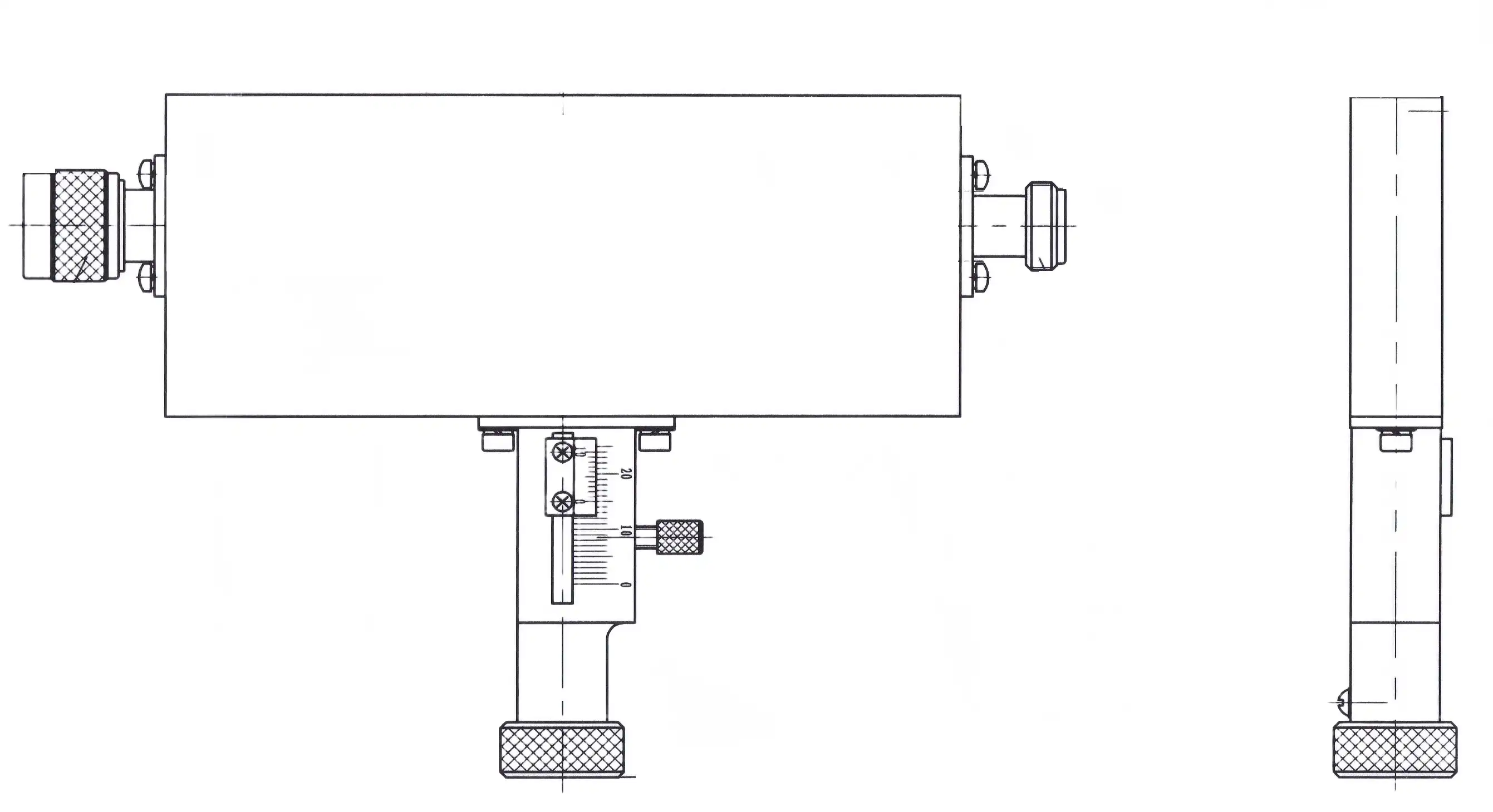
Coaxial variable attenuators lower the signal amplitude by using resistive elements that can be changed all the time. These elements are usually controlled by hand knobs or micrometer drives. With this analog method, there is endless resolution within the given attenuation range, which lets for exact tuning in the lab or out in the field. The internal resistive networks keep the impedance matching at 50 ohms across a wide range of frequencies, from DC to millimeter-wave bands that go over 110 GHz in high-performance models. Some important specs are insertion loss (the loss that happens naturally at 0 dB, which is usually less than 0.5 dB), voltage standing wave ratio (VSWR), which shows how well the impedance matches, and attenuation flatness, which shows how consistently the device works across its frequency band.
Design Characteristics of Step Attenuators
Step attenuators work in different ways from a coaxial variable attenuator. They use mechanical turrets or electronic PIN diode networks to change between specific reduction levels, like 1 dB, 5 dB, or 10 dB steps. For automated test equipment (ATE) systems, this architecture is highly repeatable, which means that the same attenuation value gives the same results over and over again. Step attenuators make it easier to add them to programmable systems where microcontrollers or software interfaces can set precise attenuation states for testing many RF amplifiers or transceivers at once. Because they are fixed-step, they give up some analog flexibility in exchange for higher numerical accuracy, less mechanical wear, and an easier way to track calibration.
Critical Technical Specifications for B2B Procurement
When buying, workers look at attenuators; they have to look at a number of factors that aren't related to attenuation range. The device's ability to handle power decides whether it can work in high-power transmitter settings. Going over the average or peak power levels damages the resistive element. In vector network analyzer (VNA) setups, measurement accuracy is directly affected by frequency flatness, which is shown as a change in decibels across the operating band (for example, ±1.0 dB at 18 GHz). The types of connectors (SMA, N-Type, and 2.92mm) determine how well they work with current systems. ISO 9001 approval and RoHS compliance show that the product meets quality and environmental standards that are important for defense and aerospace uses.
Technical Tradeoffs Between Coaxial Variable and Step Attenuators
Accuracy, Repeatability, and Noise Performance
There is some uncertainty in coaxial variable attenuators because of the way the dials are made. Depending on the quality of the design, the accuracy can be anywhere from ±0.5 dB to ±5%. Their continuous adjustment is flexible, but there may be some hysteresis where moving the dial forward or backward gives slightly different results. This problem is fixed by discrete switching in step attenuators, which makes the limits tighter and the accuracy almost perfect—every click to a certain attenuation level gives the same results that can be traced back to calibration standards. But electronic step attenuators that use PIN diodes can add low-level phase noise, which is a problem for testing very sensitive receivers or using phase-coherent radar.
Insertion Loss and Frequency-Dependent Behavior
Insertion loss is present in both types of attenuators, but the amount is different. When keeping signal strength is important, coaxial variable attenuators are better because they usually have lower leftover loss at the lowest reduction settings. Parasitic capacitance and inductance make flatness worse at higher frequencies. To reduce this variation, high-quality coaxial variable attenuators use complex resistance networks. It is important for wideband applications like testing satellite transponders to have consistent performance from 3 GHz to 30 GHz. This is because step attenuators, especially those with multiple switching stages, may accumulate higher insertion loss but keep tighter flatness specifications across frequency sweeps.
Durability, Mechanical Wear, and Operational Complexity
Adjusting the dial over and over again puts a lot of mechanical stress on manual coaxial variable attenuators, wearing down the contact surfaces and changing the calibration over thousands of cycles. Rotational life testing according to MIL-DTL-3933 standards confirms longevity, but maintenance in the field is still something to think about. Step attenuators make mechanical systems simpler. Electronic versions get rid of all moving parts, making them more reliable in harsh settings like radar systems on ships or UAV communication links. This longer durability comes at a higher cost, but it means lower maintenance costs and less downtime, which is very important for defense applications that need to be very durable.
Procurement Insights: Choosing the Right Attenuator for Your Needs
Aligning Attenuator Selection with Application Requirements
In lab tests, engineers often use coaxial variable attenuators to change signal levels over and over to test the linearity of amplifiers or find the best antenna matching networks. The analog control lets you tune in real time without any switching delays, which speeds up the approval rounds for prototypes. High-power transmitter systems, on the other hand, benefit from step attenuators' ability to handle large amounts of power and repeat themselves. Their defined levels make it easier to record for regulatory compliance and failure analysis. OEM integrators that are making RF subsystems for mass production need cost-effective solutions that balance size, connector options, and volume pricing. Because step attenuators are simpler to build, they often have better economies of scale.
Evaluating Supplier Credibility and Datasheet Transparency
Leading companies like Mini-Circuits and Pasternack keep detailed online catalogs with adjustable search tools that let buyers narrow their search by frequency range, power rate, and connection type. It is important for datasheets to clearly say the test conditions for standards. For example, an attenuation accuracy of 0.5 dB might only work at 25°C, but it would get worse in the field. Process control rigor is shown by ISO 9001 certification, and calibration against NIST standards is shown by traceability documentation. Advanced Microwave Technologies Co., Ltd. is a good example of this openness because we provide thorough technical specifications that are checked in our ISO-certified labs that are equipped with VNA systems up to 110 GHz. This makes sure that every part meets strict aerospace and defense standards.
Cost, Lead Times, and Volume Considerations
Pricing structures are very different. Coaxial variable attenuators that are tuned by hand usually cost less up front than programmable step models with digital control interfaces. But lifetime costs are different. For example, electronic attenuators lower the regularity of calibration and the cost of labor. The amount of customization affects the lead time. Catalogue items usually ship within weeks, but custom designs with specific connection genders or attenuation curves may take 8–12 weeks. When you buy more than 50 units, you can really benefit from volume discounts, especially for OEMs who use attenuators across multiple product lines. Engaging suppliers early in the design phase, which is something we encourage at ADM, lets us work together to make sure that both the performance of the parts and the cost of buying them are optimized.
Use Cases and Industry Applications Illustrating Tradeoffs
RF Testing Laboratories and Antenna Measurement Systems
Antenna pattern measures in the far field are very important in our 24-meter microwave lab at Advanced Microwave Technologies Co., Ltd. Engineers slowly change the amount of signal sent to the antenna being tested, mapping changes in gain across azimuth and elevation angles with a resolution of less than a degree. The constant control lets you precisely calibrate against reference antennas, which keeps the measuring error below 0.3 dB. Coaxial variable attenuators play a pivotal role in these measurements, where continuous control is required. Step attenuators are accurate, but their discrete jumps make it hard to pick up on small nulls in radiation patterns. This is an example of how the analog flexibility supports the mechanical complexity of the coaxial variable attenuator.
High-Power Transmitter Lines and Satellite Ground Stations
Satellite uplink systems that send kilowatts of RF power need attenuators that can work in harsh conditions without changing the signal. In this case, step attenuators are the best choice because their set resistive pads can handle higher average power levels, and separate switching means you don't have to worry about the dial moving when the device is shaken. A common C-band ground station might have a 30 dB step reduction (that goes down by 10 dB at a time) before the high-power amplifier. This lets workers lower the output while doing testing or maintenance without having to detune the whole RF chain. In this case, coaxial variable attenuators run the risk of temperature drift and power-induced failure, so the step design has to be very strong.
OEM Integration and Customized Microwave Subsystems
There are strict limits on the size, weight, and power (SWaP) of the radar modules that contract manufacturers build for defense platforms. Surface-mount technology (SMT) connectors on custom-designed coaxial variable attenuator step attenuators allow them to be directly attached to printed circuit boards, getting rid of the need for bulky coaxial cables. These small devices, which usually have an attenuation accuracy of ±0.3 dB across the X-band, can be used for phased array calibration, in which each antenna element needs its own amplitude control. At ADM, our OEM services create custom solutions that fit the needs and performance ranges of each customer. These services include prototyping help and detailed documentation, such as S-parameter files for electromagnetic simulation.
Conclusion
In the end, the choice between coaxial variable attenuators and step attenuators comes down to the priorities of the application: analog flexibility vs. digital repeatability, tuning accuracy vs. ease of use, and initial cost vs. reliability over time. Coaxial variable attenuators work best in labs and for testing prototypes, where changes made by humans and continuous control allow for more complex system optimization. Step attenuators are most common in production testing, high-power settings, and automatic systems that need to be consistent all the time. Procurement managers and RF engineers can safely choose parts that improve system performance while keeping total ownership costs low by carefully examining frequency requirements, power handling, insertion loss, and seller support capabilities. When you work with experienced manufacturers early on in the design process, you get access to customization options, technical knowledge, and quality assurances that turn choosing components from a transactional job to a strategic benefit.
FAQ
1. What distinguishes a continuous variable from a step attenuator?
With their analog dial controls, continuously variable coaxial attenuators offer infinite resolution within their attenuation range. This makes them perfect for fine-tuning during testing, where smooth adjustments are important. Step attenuators let you change the level of attenuation in clear steps of 1 dB, 5 dB, or 10 dB. This gives you better repeatability and numerical accuracy, which are important for programmable automated test systems. Coaxial variable attenuator designs work best in situations where tuning needs to happen in real time, while step models work best in situations where attenuation levels need to be stable and traceable across multiple measurement rounds.
2. How does frequency affect attenuation accuracy?
Higher frequencies add extra capacitance and inductance, that make attenuation less accurate. This is measured as frequency flatness. This difference is kept to a minimum by good attenuators; the specs may say that they are flat to within 1.0 dB at 18 GHz. To make sure the attenuator's error budget fits the system's accuracy needs, buyers must check that it is flat across the whole operating band. In more advanced designs, compensated resistive networks keep working well into millimeter-wave bands, which is important for testing 5G and using them in satellites.
3. Can variable attenuators handle high-power transmitter applications?
When high-power signals hit low-power coaxial variable attenuators, the resistive parts get too hot and permanently change their values. Always check the average and high power ratings; going over these limits will damage the gadget. For high-power uses, you need either specialized high-power variable coaxial attenuators or, more often, step attenuators made with strong resistive pads. Putting a set filter in front of a coaxial variable attenuator unit keeps it safe from too much power while still letting you make adjustments.
Partner with ADM for Precision Coaxial Variable Attenuator Solutions
Advanced Microwave Technologies Co., Ltd. has a wide range of coaxial variable attenuators and step attenuators that are designed to be reliable and work well. They can help you with your RF component purchases. We have been making microwaves for 20 years, are certified to ISO 9001:2015, and can test up to 110 GHz. This makes us a reliable seller of coaxial variable attenuators for defence, aerospace, satellite communication, and industry R&D. We are experts at OEM customisation, which means that we can give you custom attenuation ranges, connector configurations, and power ratings that work perfectly with your subsystems. Our engineering team offers full technical support, from making prototypes to mass production, making sure that your requirements are translated into parts that work better than expected. Contact craig@admicrowave.com right away to talk about your attenuation needs, get datasheets, or set up sample units. Let us help you navigate the coaxial variable attenuator versus step attenuator trade-offs with solutions backed by rigorous quality control and responsive after-sales support.
References
1. Johnson, R. T., & Williams, M. A. (2021). Precision Attenuator Design for Microwave Test Systems. IEEE Microwave Theory and Techniques Society.
2. Chen, L., & Kumar, P. (2020). Comparative Analysis of Variable and Step Attenuators in High-Frequency Applications. Journal of RF Engineering, 45(3), 112-128.
3. Anderson, K. D. (2019). Power Handling and Thermal Management in Coaxial Attenuators. Microwave Journal, 62(8), 54-68.
4. Martinez, S., & Zhao, Y. (2022). Frequency Flatness Optimization in Millimeter-Wave Attenuators. International Journal of Microwave and Wireless Technologies, 14(7), 890-904.
5. Thompson, G. H. (2018). Procurement Best Practices for RF and Microwave Components in Defense Applications. Defense Technology Review, 29(2), 33-47.
6. Lee, J. S., & Patel, N. (2020). Automated Test Equipment Integration: Attenuator Selection Criteria. Electronic Design Automation Quarterly, 18(4), 201-215.
YOU MAY LIKE
 VIEW MOREWG Adapter
 VIEW MOREWaveguide E Bend
 VIEW MORERight Angle Double Ridged WG To Coaxial Adapter
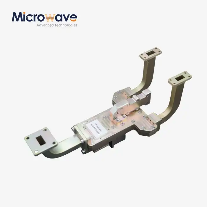 VIEW MOREMagic Hybrid Tee
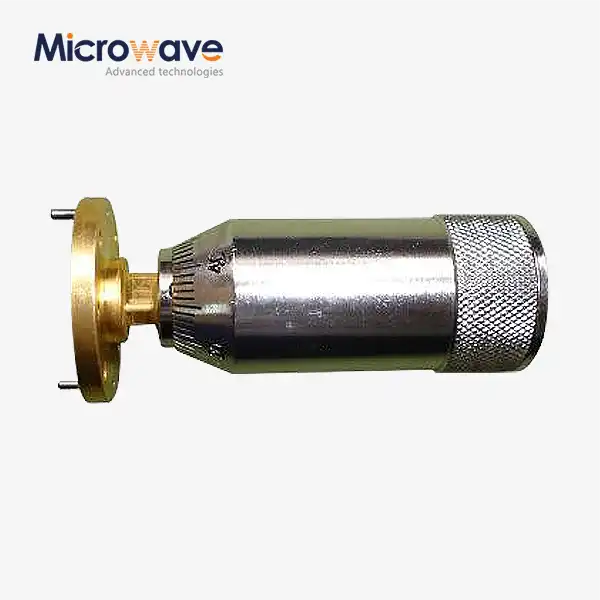 VIEW MOREWaveguide Sliding Short
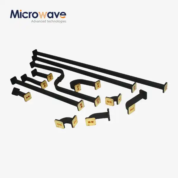 VIEW MOREDouble Ridged Flexible Waveguide
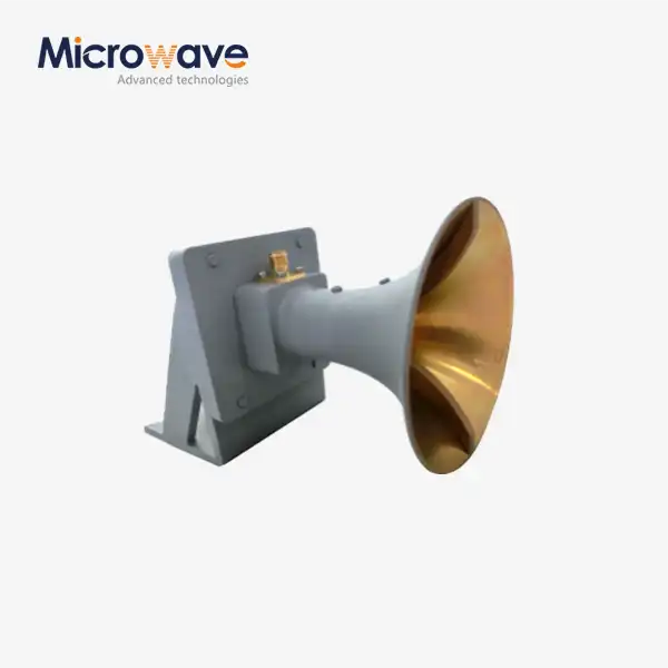 VIEW MOREUltra Double-ridged Horn Antenna
 VIEW MOREOpen Boundary Dual Linear Polarization Four Ridged Horn Antenna
