





Does Compression Rate Affect EMI Waveguide Gaskets Shielding?
The compression rate does have a direct and important effect on how well EMI waveguide gaskets protect. When these special gaskets are pressed down properly, they make close metal-to-metal contact between the sides of two flanges that fit together. This lowers the contact resistance and stops electromagnetic interference from leaking out at important waveguide joints. If you don't compress the gasket enough, tiny air holes form that let leaks happen. If you compress it too much, conductive particles inside the matrix can become forever deformed, which hurts both its mechanical integrity and its ability to conduct electricity. To get the best shielding across microwave and RF bands in mission-critical systems, you need to understand and control the compression settings.
Understanding EMI Waveguide Gaskets and Shielding Fundamentals
The Essential Role of EMI Waveguide Gaskets
Waveguide flange seals can be used for two different things besides just closing. At waveguide connections, these precision-engineered parts must protect against electromagnetic fields and the surroundings at the same time. Waveguide anti-leak gaskets are different from other gaskets because they keep signals intact while stopping moisture from entering and pressure loss in pressurised systems. A big problem in engineering that needs to be solved by good gasket design is the joint discontinuity phenomenon. This is when tiny gaps between metal plates release energy and cause insertion loss.
Material Composition and Electromagnetic Properties
Waveguide seals work because the materials that go into them were carefully chosen. These parts are made up of high-performance elastomers like silicone or fluorosilicone that are loaded with electrical particles. The conductivity is provided by silver-plated aluminium, silver-plated copper, and nickel-graphite fillers. The volume resistance is usually less than 0.010 ohm-cm. These materials hide more than 100 dB of plane wave frequencies around 10 GHz, which is important for defence radar systems, satellite ground stations, and high-precision measuring tools.
Compression's Fundamental Impact on Performance
How well the gasket of the EMI waveguide gaskets maintains electrical continuity across the flange contact is directly affected by how much it is compressed. When the gasket material is pressed against the matching surfaces, the conductive particles in the elastomer matrix move closer to the metal edges. This makes more than one path for electricity to flow. This change in the real world lowers the resistance of the contact and ensures that the RF performance stays the same across the whole frequency range. The Shore A hardness range of 65 to 85 keeps the structure strong when it is compressed, but it's still flexible enough to handle thermal cycling between -55°C and +160°C in aircraft uses.
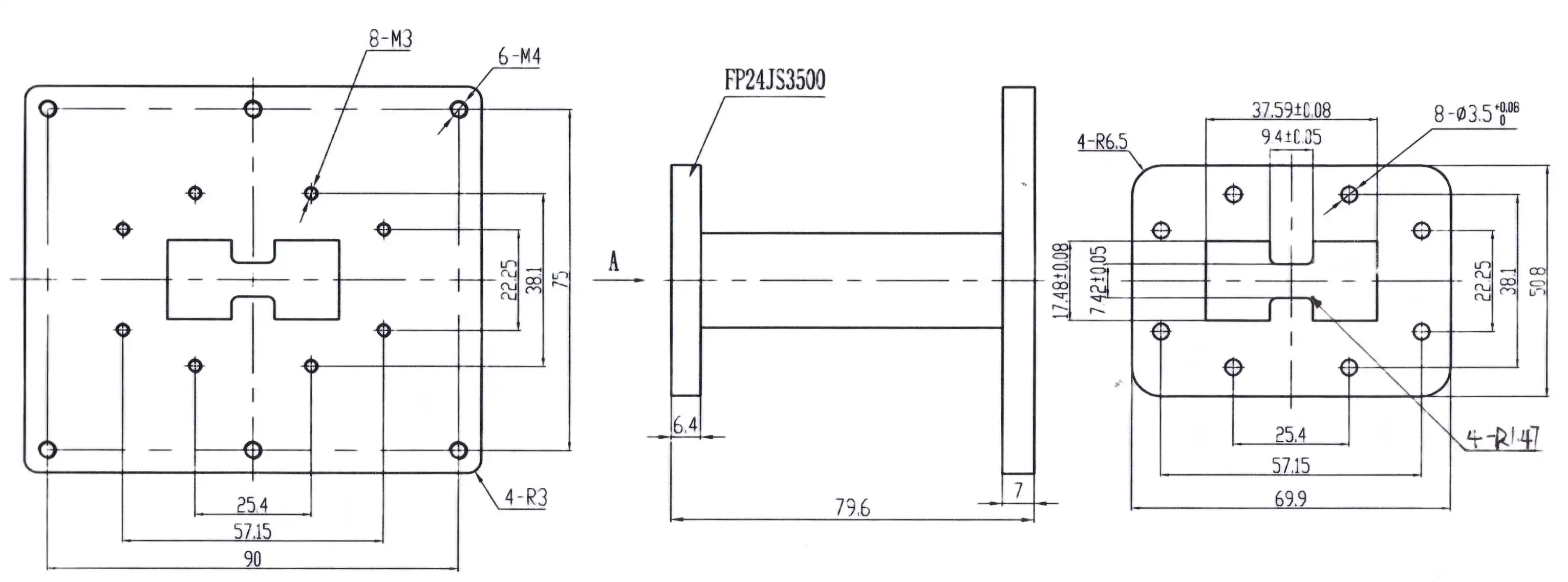
How Compression Rate Influences Shielding Performance
The Physics of Compression and Conductivity
The electrical properties at the waveguide joint are fundamentally changed by the right amount of compression. As the seal gets tighter, the conductive filler particles inside the rubber matrix get denser, making it easier for electricity to flow to the metal flange surfaces. This makes it so that there is less effective contact resistance between the gasket and both joining surfaces. This is especially important at microwave frequencies, where even very small amounts of resistance can damage the insulation. Researchers in electromagnetic compatibility labs have found that the best compression usually results in contact resistance values below 0.005 ohms. This lets them test shielding effectiveness that are regularly higher than 90 dB from DC to X-band frequencies.
Consequences of Insufficient Compression
When compression levels drop below what is considered optimal, several speed issues happen at the same time. At the contact, tiny air gaps stay, causing slot antenna effects that send electromagnetic energy out from the waveguide joint. These holes also let outside noise and clutter into the signal line, making it less clear. When purchasing, teams look at gasket performance specs, they should know that voltage standing wave ratio (VSWR) readings get worse quickly when compression falls below what the maker recommends. This impedance mismatch leads to signal echoes, which lower the system's efficiency and can hurt sensitive emitter parts in high-power situations.
Risks of Excessive Compression
Overcompression is just as bad, and it affects both short-term performance and long-term dependability. When compression forces are higher than the gasket's mechanical limits, the rubber matrix deforms in a way that can't be fixed. The conductive bits get crushed or moved around, which breaks up the even spread that is needed for shields to work. Our research team has seen that gaskets that are compressed more than 50% of their original thickness age more quickly. Over the course of their useful lives, they lose 15 to 25 dB of blocking effectiveness. In mobile systems and aircraft settings, these effects are made worse by thermal cycling and vibration.
Balancing Compression for Operational Environments
To find the compression sweet spot of EMI waveguide gaskets, you need to know about the mechanical and environmental forces that waveguide systems go through while they're working. Different levels of vibration from aeroplane engines, differences in thermal expansion between flanges made of aluminium and stainless steel, and changes in pressure in pressurised waveguide systems can all affect how compression properties change over time. Design engineers have to choose gasket materials and compression goals that keep performance margins stable over the lifecycle of the product. They have to take compression set into account, which is the constant loss of thickness that happens to elastomers over time when they are under long-term load.
Selecting and Designing EMI Waveguide Gaskets with Optimal Compression in Mind
Material Selection Impacts Compression Behavior
Different gasket materials react differently to compression forces, so choosing the right material is an important part of the buying process. Metallic seals made from beryllium copper or silver-plated aluminium alloys are very good at conducting electricity and staying stable over a wide range of temperatures. However, they need precise torque control during installation to keep them from deforming permanently. Conductive elastomer gaskets are more flexible and forgiving during installation than hard metal choices. They can work with surface imperfections and misaligned flanges. Foam-based gaskets with conductive coatings are the most flexible choice. They can form good seals with lower compression forces, but they tend to last less long in places with a lot of shaking.
When choosing between these choices, you have to weigh the needs for electromagnetic performance against the limitations of the mechanical system and your funds. The Shore hardness, compression modulus, and recovery properties of the material all affect how the gasket reacts to torque during fitting and pressures during use.
Design Considerations for Compression Optimization
The shape of the waveguide plate has a big impact on the tension profile that is put on the gasket. Standard flange designs, such as UG-style or CPR-style flanges, spread compression forces in different ways depending on the bolt pattern, the thickness of the flange, and the contact surface area. When choosing cross-sections and compression rates for gaskets, procurement requirements should take these geometric factors into account. For the best balance between shielding performance and mechanical life, our technical team suggests gasket thicknesses that achieve 25–35% compression at suggested torque values.
Real-World Application Examples
In 2022, we helped with a satellite ground station project that shows how useful compression optimisation can be in real life. The system programmer first asked for standard conductive elastomer covers for Ka-band waveguide runs, but field tests showed that the shielding wasn't working as well as expected at a few flange joints. It was found that switching between day and night activities caused different amounts of expansion between the aluminium waveguide sections and the stainless steel mounting gear. This changed how the gaskets were compressed at the interfaces. We changed the gasket's requirements so that it would use a higher-temperature fluorosilicone substance with different compression properties. This kept the contact pressure constant from -20°C to +60°C. After the changes were made, tests showed that the protection worked 18dB better at the problem frequencies.
Installation Best Practices to Ensure Proper Compression
Surface Preparation Requirements
To get uniform tension, the mating flange sides must first be properly prepared. Any dirt, oxidation, or rough spots on the surface will make small holes that make covering and protecting less effective. Use rubbing alcohol and lint-free wipes to clean the flange surfaces and get rid of any gasket material that is still there from previous installs. Waveguide uses need tighter tolerances than most RF connector interfaces, so look at the surfaces under a microscope to make sure they are flat within 0.002 inches across the closing circle.
Torque Specifications and Fastening Sequences
The right bolt pressure makes sure that the tension is spread out evenly around the gasket's edge. Manufacturer datasheets usually list torque values that depend on the size of the bolt and the material of the flange. For regular waveguide flanges, these values are usually between 15 and 45 inch-pounds. Instead of tightening each bolt one at a time to the final standard, apply torque in a star design, gradually raising the tension over multiple passes. This method keeps the seal from distorting and makes sure that the compression is even.
Verification and Measurement Procedures
Verification makes sure that compression goals have been met after installation. When you put a feeler gauge around the edge of the flange, it should always meet resistance, which means that the gasket is being compressed evenly. In more complex setups, compression indicator features may be used. These are small marks or mechanical signs built into the gasket design that show that the compression is correct. Using handheld spectrum analysers or network analysers to measure shielding efficiency is the only way to be sure of the system's performance before it is put into service.
Maintenance and Troubleshooting Strategies
At regular times, the state of the gasket and its ability to hold air should be checked. Thermal cycles and shaking slowly break down the properties of elastomers through compression set. This shows up as thinner gaskets and less closing force. When measures of shielding performance show that it is getting worse, replacing the cover is usually the most cost-effective way to fix the problem. Procurement teams should set replacement plans based on how harsh the environment is. For example, high-vibration mobile applications should be replaced every year, while benign ground-based setups should be replaced every three to five years.

Procurement Considerations: How Compression Influences Buying Decisions
Interpreting Technical Datasheets
When purchasing, experts look at waveguide gasket suppliers of EMI waveguide gaskets; they need to know how to understand requirements that have to do with compression. Some important factors are the suggested compression range, which is usually given as a percentage of the original thickness, the compression set after thermal ageing (ASTM D395), and the efficiency of the shielding across the working frequency band at the stated compression levels. Reputable makers give thorough performance curves that show how effective shielding is compared to compression. This helps customers make smart choices about which product to buy. When you are comparing goods, make sure that the test settings, especially the frequency range, temperature extremes, and compression method, are the same as the ones you will be using.
Evaluating Total Cost of Ownership
Unit price naturally affects choices about what to buy, but compression features have a big effect on the total cost of ownership. Gaskets that keep their compression qualities stable over long periods of service save money on repair labour and system downtime. In situations where replacing a gasket involves shutting down the system or sending out a specialised expert, a gasket that costs 40% more but lasts twice as long is a better deal. Our purchase analysis tools use data from compression sets to project how often things will need to be replaced. This helps them figure out realistic lifetime costs.
Supplier Capability and Customization Options
Standard catalogue seals work well for many uses, but mission-critical systems often need to be customised. During the qualification step, talk to possible providers about your compression needs to see how well they can help with engineering. Can they change the way elastomers are made to get the best compression properties for your temperature range? Do they offer compression tests to make sure the software works well before it is used in production? In-house material labs at Advanced Microwave Technologies Co., Ltd. are prepared to create custom gasket formulas that meet specific compression needs. The company also has measurement tools that can go up to 110 GHz to make sure the performance is complete.
The procurement process should also address lead times, minimum order amounts, and the resilience of the supply chain, which should also be part of the buying process. Speciality gaskets that are optimised for compression may need longer lead times to be manufactured than standard goods. This makes supplier dependability and inventory management very important. Having sources who keep safety stock or can speed up production is a good way to protect yourself in case you need to meet an unexpected demand.
Conclusion
The compression rate is the main factor that affects how well EMI waveguide gaskets do their important job of protecting. The right amount of compression creates the low-resistance electrical routes needed to keep electromagnetic energy inside waveguide structures while also sealing the surroundings against water and other contaminants. Both too little and too much compression hurt performance in different ways, by either creating leakage routes or damaging the material permanently. This is why precise compression control is important during the design, installation, and operation stages. If procurement teams and design engineers understand the complicated relationship between compression parameters and shielding effectiveness, they can make decisions that improve system performance, lower lifecycle costs, and make sure that systems work reliably in demanding defence, aerospace, and telecommunications applications.
FAQ
1. What compression rate typically provides optimal shielding for waveguide gaskets?
Most waveguide gasket makers say that the thickness of the compressed gasket should be between 25% and 35% of its original thickness. This range lets the conductive seal material touch the flange sides closely without changing shape permanently. Different types of materials need different amounts of tension to work best. For example, metallic seals need more control than flexible ones.
2. How does temperature affect gasket compression over time?
Elastomer materials go through compression set, which is a lasting loss of thickness under steady load, when they are heated and cooled many times. When gaskets are used in places where temperatures can change a lot, from -55°C to +125°C, they may lose 15 to 20 percent of their original thickness over the course of several years of use. This can make them less compressible and possibly less effective at protecting.
3. Can I reuse waveguide gaskets after disassembly?
It is usually not a good idea to use gaskets more than once, especially after they have been fully compressed and heated and cooled several times. The initial compression set changes the structure of the material in a way that can't be undone, so the gasket can't return to its original compression properties when it's put back in place. For important uses, you should always use new seals when putting things back together.
Partner with ADM for Superior EMI Waveguide Gasket Solutions
Advanced Microwave Technologies Co., Ltd is ready to be your reliable source for EMI waveguide gaskets. They offer precision-engineered sealing solutions and have over 20 years of experience in RF and microwave technology. Our engineering team knows how important it is to find the right mix between compression properties and protecting performance. We offer both standard catalogue items and fully customised gasket designs that are made to fit your exact needs. If you need waveguide anti-leak gaskets for pressurised satellite communication systems or specialised flange gaskets for defence radar applications, our ISO 9001:2015 certified production methods will make sure that the quality is always the same and the products work well. Email our technical experts at craig@admicrowave.com to talk about your unique compression needs, get performance data, or look into making a custom seal for your next project.
References
1. White, Donald R.J. Handbook of Electromagnetic Interference and Compatibility: EMI Test Methods and Procedures. Gainesville, VA: Interference Control Technologies, 2018.
2. Ott, Henry W. Electromagnetic Compatibility Engineering. Hoboken, NJ: John Wiley & Sons, 2020.
3. Hemming, Len H. Architectural Electromagnetic Shielding Handbook: A Design and Specification Guide. Piscataway, NJ: IEEE Press, 2019.
4. Paul, Clayton R. Introduction to Electromagnetic Compatibility, 2nd Edition. Hoboken, NJ: John Wiley & Sons, 2017.
5. Kodali, Prasad V. Engineering Electromagnetic Compatibility: Principles, Measurements, Technologies, and Computer Models. New York, NY: IEEE Press, 2021.
6. Williams, Tim. EMC for Product Designers: Meeting the European EMC Directive, 5th Edition. Oxford, UK: Newnes Publishing, 2016.
YOU MAY LIKE
 VIEW MOREWaveguide Loop Coupler
 VIEW MORERight Angle Double Ridged WG To Coaxial Adapter
 VIEW MORERight Angle Waveguide to Microstrip Adapter
 VIEW MOREEnd Launch Waveguide to Microstrip Adapter
 VIEW MOREStandard Horn Antenna
 VIEW MOREMMDS Transmitting Antenna
 VIEW MOREUltra Double-ridged Horn Antenna
 VIEW MOREConical Linear Polarization Horn Antenna
