Does Rotary Precision Affect Variable Waveguide Attenuator Accuracy?
Yes, rotary precision significantly influences variable waveguide attenuator accuracy. The mechanical resolution of the rotary vane mechanism directly determines how precisely attenuation levels can be adjusted and repeated. When you work with high-frequency RF systems where signal integrity matters, even minor deviations in the rotary positioning translate to measurable errors in insertion loss. Variable waveguide attenuators rely on the precise angular movement of an absorbing element within the waveguide structure. Without adequate rotary precision, the device cannot maintain consistent attenuation settings, compromising calibration stability and measurement reliability critical for radar testing, satellite ground stations, and defense applications.
Understanding Variable Waveguide Attenuators and Rotary Precision
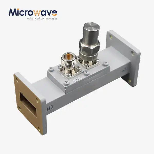
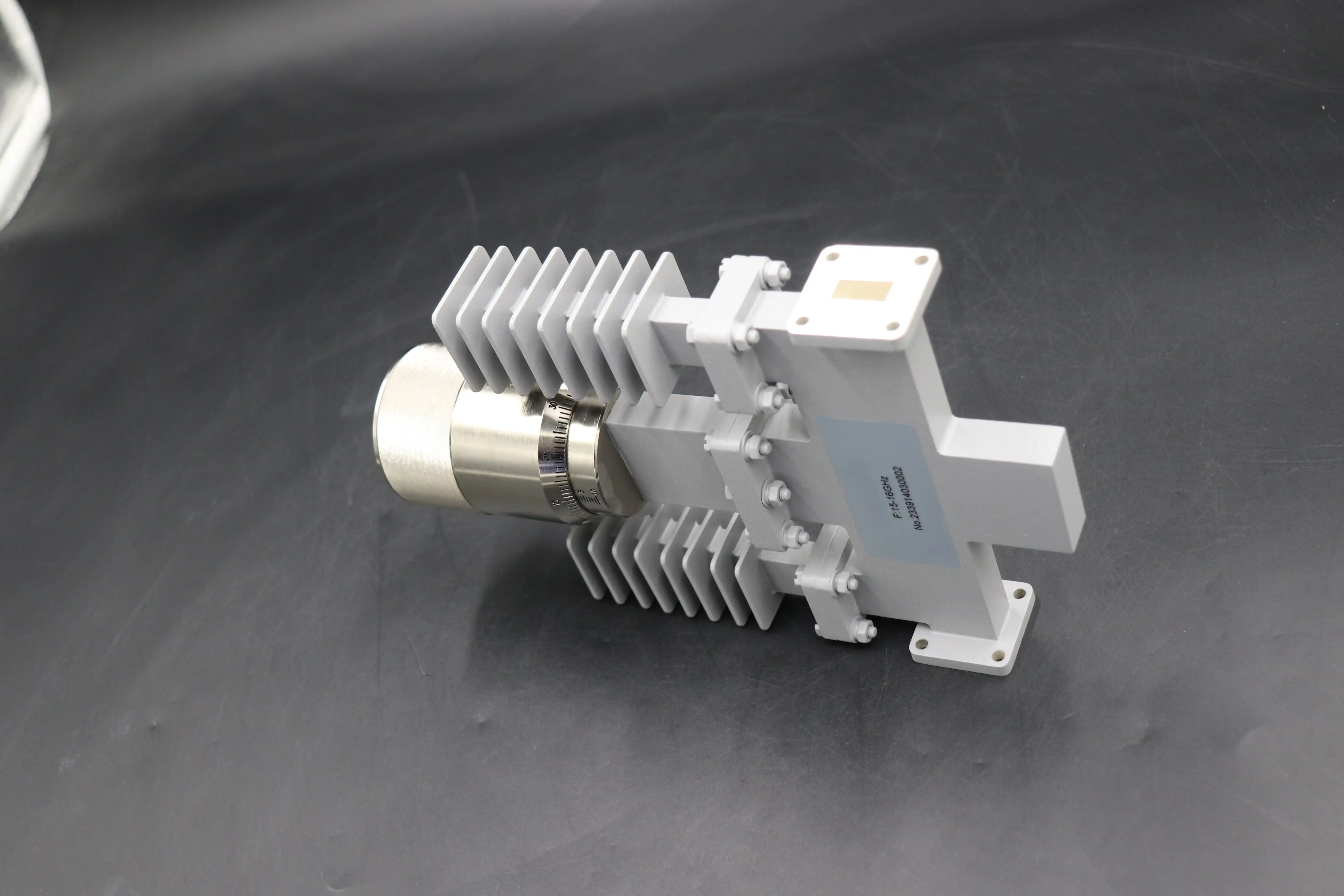
A variable waveguide attenuator is a very accurate microwave part that controls and changes the intensity level of electromagnetic signals moving through a waveguide transmission line. Unlike fixed attenuators, it lets the reduction be changed continuously or in steps, usually from 0 dB to 60 dB or higher, without stopping the signal flow. This is done mechanically by putting a resistant dielectric blade into the waveguide's electric field. More energy is received as the vane goes deeper into the field. This lets the signal strength be changed on the fly.
These parts fix important problems in the business. Variable attenuators are used to test satellite communication earth stations. They mimic situations like path loss or rain fade, which lets engineers find bit error rate limits without having to move antennas physically. Before the signal gets to the testing equipment, the output of high-power travelling wave tube amplifiers can be stepped down. This helps calibrate radar systems and keeps expensive vector network analysers from overheating. Research groups that work with millimetre waves above 75 GHz need waveguide-based reduction because coaxial connections lose too much signal at these frequencies.
Operating Principles and Rotary Mechanisms
The rotating device is what makes it possible to change the settings on a variable waveguide attenuator. A standard rotary vane design has an absorbing element that is carefully machined and placed on a shaft. The vane changes its position in relation to the electromagnetic field moving through the waveguide when the operator turns the shaft. The amount of attenuation is based on how much the fields combine. To get a resolution of as little as 0.01 dB, high-end units use precision bearings, dials that have been measured, and micrometre changes.
Different companies use different rotating precise technologies in a variable waveguide attenuator. Some use worm gears to cut down on torque and make things more repeatable. Others use ball detents or friction locks to keep the place even when the machine is shaking. The attenuator's ability to consistently repeat the same reduction value when set back to a certain dial setting depends on how well these systems are made mechanically. Advanced Microwave Technologies Co., Ltd. has made rotary mechanisms that have been tried in a range of weather conditions and vibration levels that meet MIL-DTL-3933 standards. These mechanisms are reliable in aircraft and defence settings.
Applications Across Industries
These attenuators are used by telecom system designers to test the dynamic range of antennas and characterise satellite modems. They are needed by radar calibration labs to figure out the accuracy of amplifiers without damaging delicate measuring tools. From working with defence companies, we know that acquisition teams look for attenuators that can handle peak power of kilowatts while keeping VSWR low (usually below 1.15:1) across the entire attenuation range. Waveguide-based systems are the only ones that can be used in mission-critical situations because they can handle a lot of power, can be adjusted precisely, and are built to last.
How Rotary Precision Impacts Attenuator Accuracy: Technical Analysis
There are two main things that make up rotary precision: resolution and consistency. Resolution is the smallest change in reduction that the device can make. Repeatability is a measure of how often the device returns to the same reduction value after being set to the same point on the dial. Both of these factors have a direct effect on the total accuracy of the attenuator, which for high-quality rotary vane types is usually given as ±0.1 dB or 2% of the reading.
Mechanical Factors Affecting Precision
When there is play between parts that fit together in the rotating drive system, this is called mechanical backlash. A small amount of angle backlash at the shaft can cause a mistake of several tenths of a decibel in how loud the sound is. The vane position changes in relation to the electromagnetic field because the shaft wobbles, which is a movement perpendicular to the axis of spin. We've seen that attenuators that don't have enough bearing support lose their attenuation as the shaft angle changes. This is especially clear when going from low to high attenuation sets.
Mechanical limits are made worse by environmental factors. When the temperature changes, the waveguide body and rotary device expand at different rates. It is possible for humidity to cause rust or change the dielectric qualities of objects that absorb electricity. If the right locking devices aren't used, vibrations in mobile radar sites or platforms in the air can move the rotary position. At Advanced Microwave Technologies Co., Ltd., we test mechanical stability by cycling the temperature from -40°C to +85°C and creating vibration patterns that fit the conditions of an aeroplane mounting.
Relationship Between Positioning and Insertion Loss Control
When the frequency range is very large, the link between accurate rotating positioning and stable insertion loss becomes very important. A variable waveguide attenuator that works in the X-band (8.2 to 12.4 GHz) must keep the same level of reduction at both band ends. Because the electromagnetic field changes with frequency, even a small angle shift of the vane can lead to mistakes in frequency-dependent attenuation. Precision rotation control makes sure that the rotor always intercepts the field, no matter what the working frequency is. This keeps the attenuation response flat across the band.
Engineers use attenuation accuracy to set known reference values when they adjust measurement systems or describe amplifier gain compression. An attenuator with bad rotating precision adds error to the measurement chain, which lowers the accuracy of the whole system. Acceptance testing facilities for satellite transponders can't stand attenuation mistakes bigger than 0.2 dB, so rotary accuracy is an important requirement that can't be skipped.
Comparing Variable Waveguide Attenuators: Rotary Precision vs Other Design Factors
While rotary precision has a big effect on performance, other design factors also affect how well an attenuator works. When procurement pros understand these trade-offs, they can make better choices based on the needs of the application.
Variable vs Fixed Attenuators
Because they don't have any moving parts, fixed waveguide attenuators are more stable over time. They get the right amount of attenuation by using resistive cards or pieces that are carefully cut to the right size. But they are not very flexible. If you need to test cases with more than one attenuation level, you would need more set units, which would make things more expensive and difficult. While variable waveguide attenuators allow for adjustments, they also introduce mechanical flaws. If the flexibility of the application supports a little more doubt, then the choice between set and variable configurations is yours.
Rotary Waveguide vs Electronic and Optical Alternatives
Electronic attenuators that use PIN diodes or voltage-controlled devices can switch quickly and can be managed from a distance. But they can't handle the amount of power that waveguide designs can. Because metals can get rid of heat, and air is dielectric, a circular waveguide attenuator can constantly get rid of hundreds of watts. At microwave bands, electronic models can only handle milliwatts or a few watts. In photonic systems, optical attenuators are used for very different things and can't be easily compared.
When you compare makers, you can see that they deal with rotary precision problems in different ways. Pasternack has affordable models that can be used in any lab. These models have a resolution of about 0.1 dB and an accuracy of ±0.3 dB. For measurement uses, Maury Microwave has precision micrometre drives that can achieve a level of 0.01 dB. Advanced Microwave Technologies' product line strikes a balance between accuracy and durability by using strengthened bearings and materials that don't rust, making them suitable for use in outdoor phone systems and radar systems on ships. Customers can tell us what reduction range, frequency band, and mechanical contact requirements they need so that our products can fit their specific needs.
Procurement Considerations for Variable Waveguide Attenuators
To choose the right variable waveguide attenuator, you have to compare the requirements to what the application needs while also taking supply chain factors into account.
Interpreting Technical Specifications
It is important for datasheets to make it clear what the attenuation range, frequency coverage, VSWR across the adjustment range, power handling capacity, and precision standards are. Rotary precision is shown by the accuracy rating. If measurement accuracy is important, look for devices that are marked ±0.1 dB or better. Check to see if the accuracy is given as a fixed number or a percentage of the setting. This can change the size of the mistake at different levels of reduction. An insertion loss of 0 dB means that there is residual loss; numbers below 0.5 dB are common for good systems.
For vector readings, phase stability specs are important. Some rotary vane attenuators only change the phase a little when they are adjusted, while others change the phase a lot. Make sure that the power handling rates are right for the job. Both the normal power and the peak power are important, especially in pulsed radar systems.
Balancing Cost Against Performance
High-precision spinning gears that can be adjusted with micrometres and are calibrated in a lab are very expensive. Check to see if your program really needs 0.01 dB sharpness or if 0.1 dB will do. When measuring "go" or "no-go," production test systems can usually handle wider ranges of errors than testing labs that keep national standards. To make choices that are good for the economy, you should compare the cost of measurement error to the difference in the prices of the attenuators.
Planning for procurement is affected by minimum order numbers and wait times. Standard waveguide bands like X-band and Ku-band usually have faster delivery times than millimeter-wave frequencies, which need to be machined in a special way. Custom designs, like certain types of flanges, longer shafts, or weatherproof housings, take more time to build. By asking for samples to be tested, you can make sure of the rotating feel, mechanical quality, and electrical performance before committing to large amounts. Our team at Advanced Microwave Technologies can usually get sample units to you in less than three weeks. This will help your testing plan and give you room to make changes to the specifications.
Best Practices to Ensure Optimal Accuracy in Use
As the first step, buying an accurate variable waveguide attenuator is important. If you set up, handle, and maintain something correctly, it will work well for a long time.
Installation and Handling Guidelines
Make sure the attenuator has enough mechanical support so it doesn't bend, which could damage the waveguide flanges and cause losses. Tightening flange bolts too much can damage the VSWR and bend the flanges, while not tightening them enough can cause leaks. Allow access to the rotating shaft for adjustments, but keep dirt and other things from getting on it. If the location is outside, you might want to think about using environmental covers to protect the system from rain and extreme temperatures.
Do not push too hard on the rotating adjustment. If the resistance goes up, look into possible binding instead of adding too much pressure, which could damage the bearings or bend the vane. Use rubbing alcohol and lint-free cloths to clean the flange sides before connecting them. Reflections that mess up readings are caused by metal particles or oxidation between the rings.
Calibration and Maintenance Programs
Regular testing is needed to check the quality of the attenuation against norms that can be tracked. The time between rounds relies on how often the device is used and how exposed it is to the environment. For example, every three months is good for demanding situations, while once a year is fine for labs. Keep track of degradation trends that could mean bearing wear or rotor damage by writing down the results of the assessment.
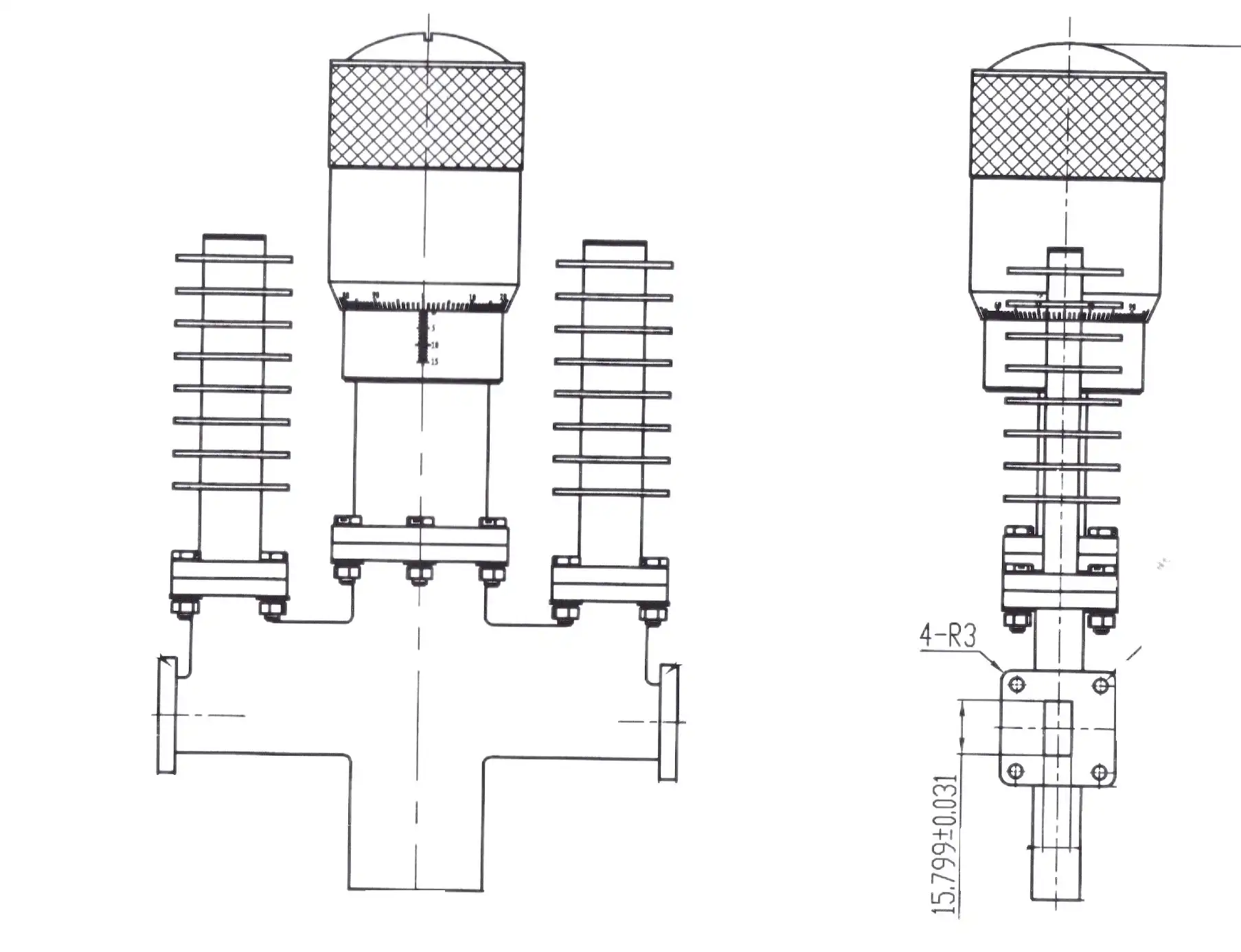
For sealed rotating devices, maintenance needs to stay low, but they go up for units that are used in the field. Look for rust, looseness, or unusual friction in mechanical parts during testing events. Some designs work better if the bearings are oiled every so often with dry oils that can work in vacuums if the attenuator is used in satellite testing rooms. Keep an eye on the VSWR and insertion loss across the frequency range. Deviations from the normal range can mean that there is internal damage that needs to be fixed or replaced.
Real-World Application Examples
After 18 months of being exposed to salt air, the attenuators used by a defence firm that ran radar sites along the coast lost their accuracy. The rotating bearings were found to be corroded after an investigation. By switching to our marine-grade design with sealed bearings and gold-plated interior parts, we were able to stop failures from happening again and again and keep calibration intervals at 12 months, even in difficult conditions.
An assembler for a satellite ground station had to describe the receiver dynamic range over a 2 GHz bandwidth. Because of inconsistent rotating placement, standard attenuators had accuracy differences of ±0.5 dB across the band. When they were upgraded to precision rotary vane units with micrometre control, the error dropped to ±0.15 dB. This made it possible to accurately figure out the receiver compression characteristics that were needed for link budget validation.
Conclusion
In conclusion, rotary precision is a key factor in determining the accuracy of a variable waveguide attenuator because it has a direct effect on how repeatable the setting is and how stable the machine is. The relationship between shaft angle and attenuation level depends on where the vane is placed exactly in the electromagnetic field. This means that mechanical errors are very important for the total performance. Prior to making a purchase, you should compare the rotary precise specs to the needs of the application, keeping cost and the level of performance assurance your system needs in mind. Accuracy is maintained throughout the life of an operation by using the right construction methods and upkeep schedules. When engineering teams and procurement professionals know about these things, they can choose attenuators that work well in demanding RF and microwave situations where signal integrity is important.
FAQ
1. What attenuation range should I specify for radar testing applications?
In radar detector tests, the signal has to be weakened from 0 dB to at least 40 dB in order to simulate signal conditions from targets far away that are weak compared to signals from targets close by that are strong. A transmitter may only need a range of 10 to 20 dB to lower high-power outputs to a safe level for measurement. Find the difference between the highest input power and the lowest signal that can be detected to make sure that your dynamic range needs are met.
2. How does waveguide size affect attenuator performance?
The frequency band range is based on the size of the waveguide. WR-90 works with the X-band (8.2-12.4 GHz), and WR-28 works with the Ka-band (26.5-40 GHz). As the frequency goes up, smaller waveguides are more affected by mechanical flaws, which makes rotational accuracy more important. Smaller waveguides can't handle as much power because they have less cross-sectional area for heat absorption.
3. Can variable waveguide attenuators handle pulsed power?
Yes, waveguide designs are better than coaxial designs at handling burst power. Peak power handling in the kilowatt range is possible thanks to the air insulator and spread metallic absorption. Make sure that the specs for both average power and peak power match your pulse width and duty cycle to avoid thermal damage or arc-over during high-power bursts.
Partner with ADM for Precision Variable Waveguide Attenuator Solutions
Advanced Microwave Technologies Co., Ltd has been making microwave parts for more than 20 years and can meet your most specific needs. Our variable waveguide attenuators have precise rotary parts that have been tested to flight standards. They give your important uses the accuracy they need. We work with defence contractors, satellite transmission providers, and study institutions all over the world, as well as in the United States. Our ISO 9001:2015-certified production facilities and 24-meter microwave lab allow full testing from 0.5 to 110 GHz, making sure that every attenuator meets requirements before it is shipped. Our engineering team is here to help you with any questions you have during the whole buying process, whether you need standard configurations or OEM solutions that are specifically made for your frequency bands and mechanical connections. Get in touch with craig@admicrowave.com to talk to one of our experts about your application needs and find out why top companies choose ADM as their variable waveguide attenuator provider for mission-critical systems.
References
1. Collin, R. E. (2001). Foundations for Microwave Engineering, 2nd Edition. IEEE Press, Wiley-Interscience.
2. Pozar, D. M. (2011). Microwave Engineering, 4th Edition. John Wiley & Sons.
3. Saad, T. S. (1971). "Microwave Engineers' Handbook, Volume 1." Artech House.
4. Harvey, A. F. (1963). Microwave Engineering. Academic Press, London.
5. Baden Fuller, A. J. (1990). An Introduction to Microwave Theory and Techniques, 2nd Edition. Pergamon Press.
6. MIL-DTL-3933 (2018). "Detail Specification: Attenuators, Fixed and Variable, Waveguide and Coaxial." United States Department of Defense.