





Crossguide Coupler for Waveguide Systems: Design Insights
A crossguide coupler represents a specialized directional coupling device that extracts or injects signals within waveguide transmission systems with exceptional precision. These components enable engineers to monitor signal power, measure reflected energy, and split signals across perpendicular waveguide planes while maintaining excellent isolation characteristics. Unlike conventional side-wall couplers, crossguide designs position coupling apertures strategically to achieve broadband performance and superior directivity, making them indispensable in satellite ground stations, radar systems, and high-frequency measurement equipment where signal integrity cannot be compromised.
Understanding Crossguide Couplers: Principles and Performance
Core Operating Principles
The operational foundation of crossguide couplers rests on controlled electromagnetic field interaction through precisely dimensioned coupling apertures positioned between two perpendicular waveguides. When a signal is sent through the main waveguide, a carefully designed fraction pairs into the secondary guide through these holes. This perpendicular geometry naturally separates the forward and backward signal routes very well, which lowers measurement error and interference in sensitive applications.
Performance Metrics That Matter
We've seen that the coupling mechanism depends on the size, shape, and placement of the apertures to get desired coupling coefficients, which are usually between 10 and 30 dB in production systems. Directivity performance is a measure of how well the device tells the difference between forward and reflected waves. Modern crossguide designs achieve directivity levels above 40 dB over large bandwidths, which is a necessary condition for accurate power readings in transmission lines.
When system integrators look at waveguide components, insertion loss is the most important thing they should think about. A quality crossguide coupler rarely adds more than 0.2 dB of loss to the main transmission path across all operational frequencies. This low-loss property preserves signal strength in long waveguide runs common in satellite ground infrastructure and phased array antenna systems.
Application Context Across Industries
Application fit is based on frequency response bands. Wideband designs can cover octave ranges or more, while narrowband designs may only cover 10-15% of the bandwidth. This wide bandwidth comes from multi-aperture designs that account for changes in coupling that happen with frequency, keeping the flat coupling response across X-band, Ku-band, or Ka-band frequencies, based on the size of the waveguide.
Premium components are different from regular ones because they can handle more power and stay stable at higher temperatures. In aerospace and defense uses, waveguide systems are exposed to temperatures ranging from -55°C to +85°C, requiring materials and construction techniques that maintain electrical performance across this range. High-power radar transmitters need couplers that can handle continuous waves up to a kilowatt level without voltage breakdown or thermal distortion.
For sending power tracking and receiver protection, satellite ground stations utilize cross- guide couplers. When ground terminals talk to geostationary satellites, operators have to make sure that the power being sent stays within licensed limits and that sensitive low-noise amplifiers are not overloaded. Properly configured couplers provide the measurement taps and signal routing that are needed for these two tasks.
Defense radar systems depend on these components to sample the transmitter output and measure the antenna pattern. During radar operation, a small amount of the power that is sent couples to monitoring receivers that check system health and look for possible component problems before they affect the task. Military specifications set strict standards for mechanical strength, electromagnetic compatibility, and environmental sealing that determine how things are made and checked for quality.
Telecommunications infrastructure benefits from crossguide implementations in point-to-point microwave lines and wireless backhaul systems. Network operators need accurate measuring points to set up systems and keep an eye on how well they're working. The crossguide coupler provides precise signal monitoring capabilities, while its low insertion loss and high isolation characteristics ensure that measurement hardware doesn't degrade link budgets while providing accurate data for network optimization.
Crossguide Coupler vs. Other Coupler Technologies: Comparative Analysis
Design Architecture Comparison
Directional couplers come in multiple architectural variants, each with distinct advantages. Bethe-hole couplers have small circular apertures and are small, but they usually have low bandwidth and poor directivity. Multi-hole designs improve bandwidth through carefully spaced aperture arrays, though they make manufacturing more difficult. Crossguide couplers place coupling elements so that they are perpendicular to the main waveguide, inherently achieving superior isolation through geometric separation.
Coaxial directional couplers are used in situations where smaller sizes and lower frequencies are needed. Their coupled-line design works well below 18 GHz, but as the frequency goes up, they lose more power and have to be made with tighter limits. At millimeter-wave frequencies, where coaxial losses become too high, waveguide-based solutions, such as crossguide designs, naturally perform better.
Hybrid couplers—including magic-T and rat-race configurations—split signals evenly instead of taking out small samples. They are useful for dividing and combining power, but they do not monitor systems as monitoring couplers do. Procurement teams need to distinguish between 3 dB hybrid couplers used for signal distribution and directional couplers with 20 dB coupling factors designed for measurement taps.
Performance Trade-offs
Different types of couplers have very different power handling capacities. Large conductor dimensions and air dielectric make waveguide designs naturally able to handle high power levels, routinely handling kilowatts of continuous power. When the power level goes up, especially above 100 watts, dielectric heating and voltage breakdown limit the performance of coaxial couplers.
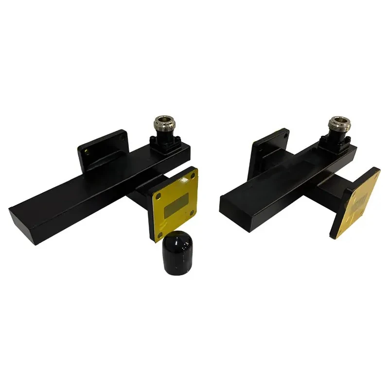
Size and weight considerations influence system integration decisions. Coaxial components are small, which is helpful in installations with limited room, while waveguide assemblies take up more space but work better at microwave and millimeter-wave frequencies. Defense and aerospace applications often accept larger waveguide components to achieve necessary reliability and power handling margins.
Selection Criteria for Procurement
Cost structures are very different between technologies. Tight control of dimensions is needed when making precision waveguides, where aperture sizes and positions must stay within sub-millimeter accuracy for proper electrical performance. This precise machining makes each unit more expensive than stamped coaxial designs, though waveguide solutions often have a better lifecycle value in mission-critical installations where the costs of replacement and downtime far exceed initial component pricing.
Technical requirements drive selection methodology. Engineering teams should evaluate frequency range against operational needs, ensuring the coupler maintains specified coupling and directivity across required bandwidths. Insertion loss budgets must account for cumulative effects across all waveguide components in signal chains, as even fractional dB losses add up in systems with multiple bends, transitions, and measurement taps.
Environmental specifications warrant careful attention. Parts that are outside need to be properly sealed against the weather, made of corrosion-resistant materials, and proven to work in extreme temperatures. ISO 9001:2015 certified production methods ensure that performance is checked across temperature ranges relevant to installed applications, from desert heat to arctic cold.
Interface compatibility avoids costly integration problems. Waveguide flange standards, including those used with a crossguide coupler, UG, WR, or custom interfaces, must match existing system hardware. Procurement specifications should detail flange types, material requirements, and any special features such as pressurization ports or alignment pins needed for specific installations.
Procurement Guide for Crossguide Couplers
Supplier Evaluation Framework
To find qualified manufacturers of crossguide couplers, you need to look at a number of credibility indicators. Industry certifications show that a company follows quality management systems; ISO 9001 certification demonstrates documented processes for design control, manufacturing, and testing. RoHS compliance matters for commercial uses subject to environmental regulations, while defense contractors need suppliers with appropriate facility clearances and export control expertise.
Advanced makers are different from basic builders because they have better technical skills. Quality suppliers operate labs with network analyzers, power meters, and far-field antenna measurement tools that characterize how well couplers work across all operating bandwidths. Validation in a Microwave Darkroom lets manufacturers test parts in configurations matching real installations, revealing performance problems that measurements done on a bench might miss.
Production capacity and customization services address project-specific needs. Some applications require standard catalog components with short lead times, while others demand custom designs optimized for unique frequency ranges, coupling values, or mechanical interfaces. Manufacturers offering OEM services help with tailored solutions and handle everything from prototype development to production scaling.
Commercial Terms and Logistics
Pricing structures reflect manufacturing complexity and order volumes. Standard waveguide components typically use tiered pricing; unit costs decrease substantially for quantities exceeding 10, 50, or 100 pieces. Custom designs involve non-recurring engineering charges that cover design optimization, tooling development, and qualification testing. Transparent suppliers provide thorough quotes breaking out these cost elements, enabling informed budget planning.
Lead times vary based on component complexity and production schedules. Catalog items with existing inventory may ship within weeks, while custom assemblies require 8-12 weeks or longer depending on design iteration cycles and manufacturing queue depth. Strategic buyers plan procurement timelines accordingly, placing orders well before integration schedules demand component delivery.
Premium suppliers are different from commodity vendors because they offer warranties and support after the sale. Comprehensive guarantees covering manufacturing defects for 12 to 24 months protect buyer investments, while expert support helps with installation questions and system integration challenges. Ongoing technical assistance ensures customers achieve optimal performance from purchased components.
Payment terms and shipping logistics require attention in international transactions. Many B2B suppliers offer net-30 or net-60 payment terms for established customers, though first-time orders may require prepayment or letters of credit. Shipping costs for waveguide assemblies, including components such as a crossguide coupler, which can be bulky and heavy, should factor into total acquisition costs, along with any customs duties or import fees applicable to cross-border purchases.
Conclusion
In conclusion, when it comes to waveguide systems that need accurate signal monitoring, high isolation, and reliable operation in harsh environments, crossguide couplers are the best choice. Because they are built perpendicularly, they have better directivity and lower insertion loss, which is why they are important for use in defense radar, satellite communications, and precise measurement. To be successful at procurement, you need to compare technical specs to application requirements, find qualified sellers through certification and capability assessments, and form partnerships that provide engineering support throughout the lifecycle of a product. These important parts will keep working reliably even as system needs change if they are installed correctly, maintained regularly, and kept up to date on new technologies.
FAQ
1. What frequency ranges do crossguide couplers support?
Crossguide couplers can work in both microwave and millimeter waves, and can be used in real life from about 1 GHz to 110 GHz. Specific frequency range depends on waveguide size—larger rectangular waveguides accommodate lower frequencies, while progressively smaller cross-sections serve higher bands. Standard designs cover established communication and radar bands, including S-band, C-band, X-band, Ku-band, K-band, and Ka-band. Custom designs address specialized frequencies for scientific instruments or military systems. When specifying couplers, ensure the operational bandwidth encompasses your full signal spectrum with margin for frequency tolerances and modulation sidebands.
2. How do coupling values affect system design?
The coupling coefficient determines what signal fraction diverts to the coupled port—typical values range from 10 dB to 30 dB. Lower coupling values (10 dB) extract more power for measurement but introduce higher insertion loss in the main path. Higher coupling values (30 dB) minimize main-line disturbance but provide smaller samples requiring more sensitive detection equipment. System designers balance these trade-offs based on available signal power, measurement receiver sensitivity, and acceptable main-path loss. Defense applications often specify 20 dB coupling as a practical compromise between adequate sample power and minimal transmission impact.
Partner with ADM for Advanced Crossguide Coupler Solutions.
Advanced Microwave Technologies Co., Ltd. is ready to help you with your waveguide system needs by providing high-quality crossguide coupler options backed by more than 20 years of experience making high-quality RF products. As a reliable global supplier, we use quality processes that are ISO 9001:2015 certified and offer a lot of customization options to make sure that the parts we send you meet all electrical and mechanical requirements. Our engineering team helps with everything, from reviewing initial specifications to helping with installation, to make sure the system works well with satellite ground stations, radar systems, and telecommunications infrastructure. Our reliable supply chain and technical know-how lower the risk of buying things and speed up project timelines, whether you need fast delivery of catalog parts or OEM designs made just for your application. You can talk to one of our applications engineers about your requirements right now by emailing craig@admicrowave.com, to explore our full range of waveguide assemblies, coaxial components, and microwave measurement solutions. We give your mission-critical systems the quality, performance, and partnership they need.
References
1. Marcuvitz, Nathan. "Waveguide Handbook." Institution of Engineering and Technology, 1986.
2. Rizzi, Peter A. "Microwave Engineering: Passive Circuits. " Prentice Hall, 1988.
3. Collin, Robert E. "Foundations for Microwave Engineering, Second Edition." Wiley-IEEE Press, 2001.
4. Montgomery, C. G., et al. "Principles of Microwave Circuits." Institution of Engineering and Technology, 1987.
5. Saad, Theodore S. "Microwave Engineer's Handbook, Volume 1." Artech House, 1971.
6. Lance, Andrew L., et al. "Microwave Theory and Applications." Prentice Hall, 1969.
YOU MAY LIKE
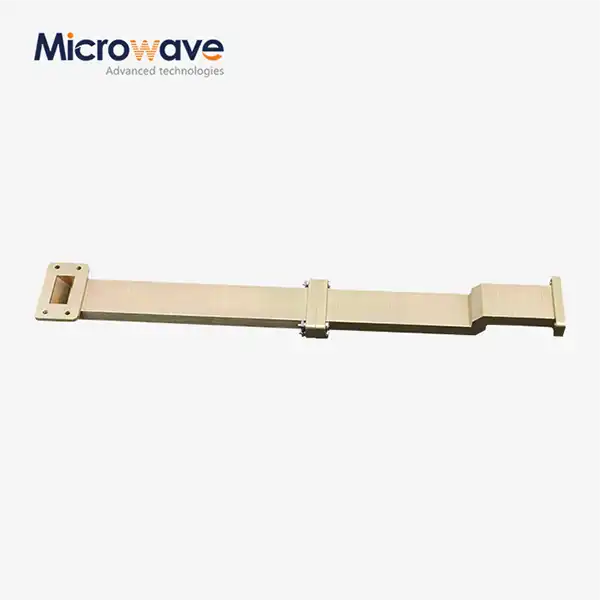 VIEW MOREWG Transition
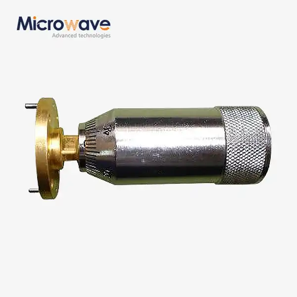 VIEW MOREWaveguide Sliding Short
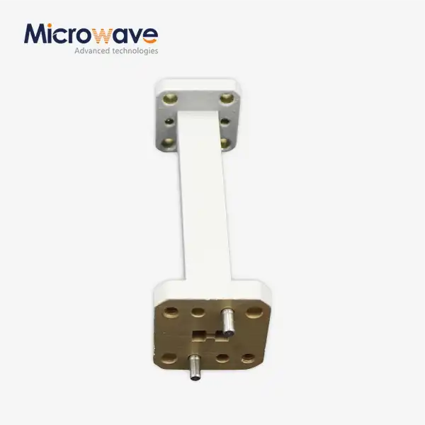 VIEW MOREDouble Ridge Waveguide Transition
 VIEW MOREDouble Ridged Flexible Waveguide
 VIEW MORECoaxial Fixed Attenuator
 VIEW MOREMMDS Transmitting Antenna
 VIEW MOREConical Dual circular Polarization Horn Antenna
 VIEW MOREDual Linear Broadband Circular Polarization Horn Antenna
