Straight Waveguide Section Guide for Microwave Engineers
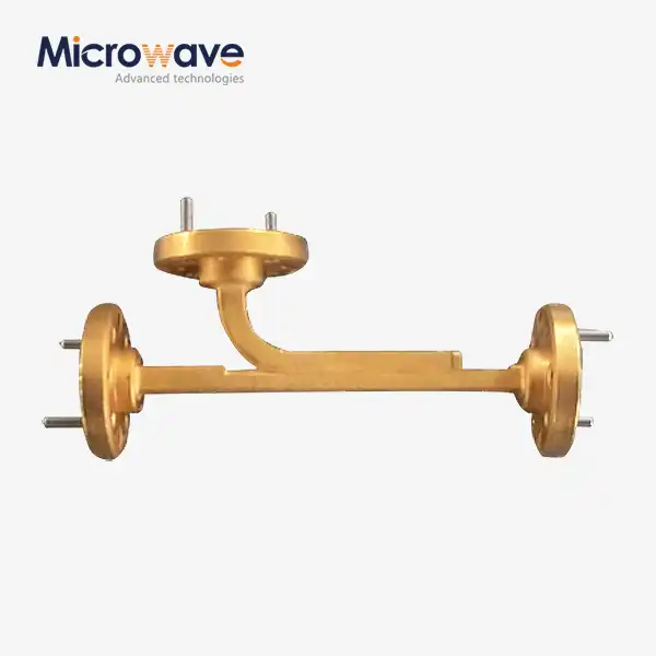
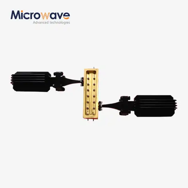
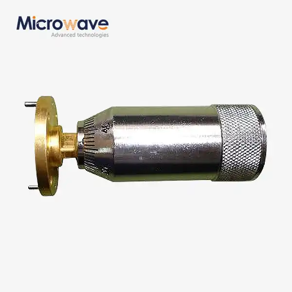
Straight waveguide sections are still very important in current RF and microwave systems when choosing precise parts for sending high-frequency signals. These hollow metal transmission lines, which can be made with square, round, or other special cross-sections, guide electromagnetic waves through internal reflection. This gets rid of the dielectric losses that happen in coaxial cables above 2 GHz. Straight waveguide sections can handle megawatt-class peak power levels while keeping the integrity of signals in mission-critical radar, satellite ground stations, and military communication systems. This is in contrast to cable bundles, which tend to break down under high power. Because they naturally block electromagnetic waves well and don't lose much of their power, procurement engineers who need stability, performance, and compliance in settings with a lot of electromagnetic fields choose these.
Understanding Straight Waveguides: Theory, Design, and Applications
Electromagnetic Wave Propagation Fundamentals
While most transmission is based on conductors, straight waveguide parts work based on boundary conditions and mode propagation. EM waves are carried by transverse electric (TE) or transverse magnetic (TM) modes. The TE10 mode is the main mode of propagation in rectangular shapes. The cutoff frequency is set by the waveguide's size. This frequency is the lower working barrier below which signal loss increases rapidly. Frequency ranges usually go from 1 GHz to more than 110 GHz, which includes L-band and W-band uses that are important for millimetre-wave research, weather radar tracking, and spacecraft telemetry.
Critical Design Parameters Affecting Performance
The choice of material has a direct effect on both how well it works electrically and how long it lasts mechanically. Aluminium metals are light and has good conductivity for business satellite communications. On the other hand, copper or brass construction is better for laboratory-grade measurement systems because it has better conductivity. The wall's thickness needs to be able to handle mechanical stress during fitting and keep its shape even when temperatures change a lot, as they do in marine and aviation systems. Gold or silver covering on the surface lowers ohmic losses at higher frequencies. This increases the working bandwidth and makes the insertion loss properties better by 0.1 to 0.3 dB per metre compared to bare metal.
Real-World Applications Across Industries
For air traffic control and navigation beacons, phased array antennas have straight waveguide sections that are shaped like rectangles. The accuracy of the angles is based on how well the phases of the different elements work together. To keep the dual-polarisation signals needed for Ka-band and Ku-band data links, satellite ground stations use circular straight waveguides in rotary joints. This also lets the antennas track. For surveillance radar that works in rough maritime conditions, where corrosion resistance and EMI shielding are important, defence contractors ask for ruggedized waveguide assemblies with MIL-STD environmental sealing. In vector network analyser calibration kits used by research institutions, precision-machined straight waveguide sections are used. Dimensional errors of less than 0.025 mm ensure accurate measurements across 0.5 to 110 GHz test ranges.
Straight Waveguide Types and Performance Comparison
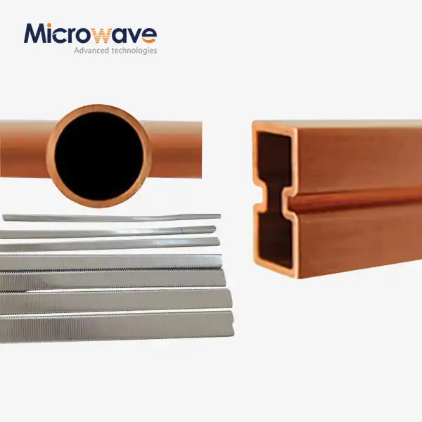
Rectangular Straight Waveguide Characteristics
The rectangular straight waveguide is still the standard for single-polarisation uses that need to know how the signal will be ruggedised. The aspect ratio of the broad and narrow walls determines the mode purity. Standardised dimensions (WR-90, WR-75, and WR-28) make sure that devices from different manufacturers can work together. Insertion loss is usually between 0.03 dB/m at X-band and 0.15 dB/m at W-band. This means that these sections can be used for short- to medium-length transmission runs in radar front-ends and test equipment. Tolerances in manufacturing have a direct effect on VSWR performance. For example, electroformed copper meets the 1.02:1 requirements set by testing standards, while precision-extruded aluminium keeps VSWR below 1.05:1.
Circular Straight Waveguide Advantages
Rotational symmetry is important for dual-polarisation systems and rotating joint assemblies, and circular cross-sections support it. The TE11 dominant mode can handle both vertical and horizontal polarisations at the same time. This gets rid of the polarisation mismatch losses that happen when rectangular shapes are mechanically rotated. Low-loss TE01 mode operation, which can be done with mode converters, lets millimetre-wave frequencies go through with as little as 0.01 dB/m of attenuation. This makes circular straight waveguides perfect for long-distance communication in radio science and deep space. Mode purity is maintained by keeping the diameter within ±0.05 mm along the whole length. This stops higher-order mode stimulation that breaks down pattern symmetry.
Performance Trade-Offs and Selection Criteria
When deciding between waveguide types and coaxial options, the ability to handle power becomes the most important issue. A WR-90 rectangular straight waveguide section with a peak power rating of 1.5 MW at 10 GHz is much more powerful than the 10 kW limit of equivalent 1/2-inch coaxial cables. When it comes to bandwidth, waveguide options are better than coaxial cables because a single waveguide covers 25–40% of the bandwidth, while various types of coaxial cables are needed for wide frequency ranges because they lose signal over time. In UAV uses, where space and weight are limited, ridge waveguide versions may be needed. These lower the cutoff frequency by 30% compared to normal rectangular designs. A cost study shows that the initial investment for a waveguide is higher than the price of a coaxial cable, but the total cost of ownership is cheaper for fixed installs because the waveguide is more reliable and doesn't need any upkeep.
How to Choose the Best Straight Waveguide for Your Application (Decision Support)?
Matching Specifications to Project Requirements
To make sure that the needs of the project are met, buying experts have to make sure that waveguide standards are met for frequency range, power handling, and weather conditions. Through cutoff frequency calculations, the operating frequency determines the physical dimensions: the waveguide width must be greater than half of the free-space wavelength in order to support propagation. Systems that need to work at 8–12 GHz need WR-90 sections, which have internal dimensions of 0.900 inches by 0.400 inches. Millimetre-wave links that need to work at 75–110 GHz need WR-10 precision, which has internal dimensions of 0.100 inches by 0.050 inches. Peak power needs to be taken into account when designing walls and flanges. For example, high-power radar emitters need pressure-tested units with choke flanges to stop arcing, while receiver front-ends look for lightweight cover flanges with little insertion loss.
Environmental and Mechanical Considerations
Marine and outdoor equipment need more than just anodising to protect against rust. MIL-STD-810 tests show that electroless nickel plating is better at resisting salt fog, while MIL-DTL-15970 chromate conversion coats provide basic defence. When temperatures change from -55°C to +125°C, which happens a lot in aircraft use, materials need to have matching thermal expansion coefficients at the flanged surfaces to stop mechanical stress and RF leaks. In aircraft systems, vibration isolation is very important. RTCA DO-160 electronics guidelines say that electrical connections must be kept during 10–500 Hz vibration patterns. This can be done with shock-mounted straight sections or flexible waveguide sections with bellows joints.
Supplier Evaluation and Quality Assurance
To find reliable straight waveguide makers, you need to check both scientific and business factors. ISO 9001:2015 certification shows that the process is consistently controlled, and RoHS compliance makes sure that the materials are in line with international rules. Full-service suppliers are different from distribution-only suppliers because they can offer custom flange configurations, non-standard lengths, and parts that are already put together. Engineers should ask for thorough test reports that include information on VSWR, insertion loss, and power handling that can be traced back to NIST standards. Manufacturers you can trust give you network tester info across the whole bandwidth, not just spot checks on a single frequency. During the system integration phases, costly delays can be avoided by getting expert help for integration, fast development, and fixing.
Procurement Guide: Buying Straight Waveguides with Confidence
Stock Versus Custom Order Strategies
Standard straight waveguide sections with common flange types (UG-style or CPR) typically ship within two weeks from established suppliers maintaining inventory. Custom configurations—including non-standard lengths, specialised flanges (cover, choke, or pressure), or integrated components like windows—can extend lead times to 4–8 weeks depending on manufacturing complexity. Budget planning should account for minimum order quantities (MOQs) often imposed on custom runs; while off-the-shelf components ship individually, specialised designs may require 10–25 units to justify tooling costs. Suppliers offering engineering services can expedite prototype quantities, enabling design validation before committing to full production volumes.
Pricing Structures and Value Assessment
Unit pricing varies significantly based on material, frequency range, and precision grade. Commercial-grade aluminium waveguide at X-band costs $50–$150 per metre, while precision copper waveguide with tight tolerances for calibration applications reaches $400–$800 per metre. Volume discounts typically begin at 25 units (10–15% reduction) and scale to 30–40% savings for orders of 100+ units. Total cost calculations must include ancillary components—flanged transitions, gaskets, and mounting hardware—which add 20–35% to the base pricing. Value assessment should weigh supplier reliability and technical support against price; the costs of downtime from component failure in operational radar systems far exceed initial procurement savings.
Building Reliable Supply Chains
International procurement for defence and aerospace programmes requires suppliers with established export compliance processes. ITAR registration and appropriate export licenses prevent shipment delays when specifications include military-standard components. Logistics assessment is crucial for bulk orders; proper packaging with foam inserts prevents flange damage during international shipping, while size constraints may necessitate sectional designs rather than full-length waveguides. Establishing relationships with authorised dealers in target markets provides local technical support and reduces customs complexities. Vendor qualification processes should document manufacturing facility inspections, quality audits, and performance history to create a vetted supplier network capable of supporting multi-year programmes.
Industry-Leading Straight Waveguide Manufacturers and Brands
Leading manufacturers in the global straight waveguide market combine decades of RF engineering experience with modern manufacturing precision. Advanced Microwave Technologies Co., Ltd. (ADM) exemplifies this integration, operating ISO 9001:2015 certified facilities equipped with measurement capabilities extending to 110 GHz. Their 24-metre anechoic chamber enables full far-field antenna characterisation, validating waveguide assembly performance in complete system contexts rather than isolated component testing. This comprehensive approach benefits procurement managers seeking turnkey solutions where straight waveguide sections integrate seamlessly with antenna feeds, power dividers, and measurement systems.
OEM partnerships distinguish manufacturers capable of delivering true custom solutions from catalogue resellers. Companies offering in-house design services translate application requirements into optimised waveguide specifications, including straight waveguide configurations, while accounting for factors like thermal expansion mismatches, multipaction thresholds in high-altitude environments, or intermodulation distortion in multi-carrier communication systems. Prototyping capabilities with sub-four-week turnaround enable iterative refinement before production commitment, reducing risk in novel system architectures. Verification through certification body databases ensures compliance with ISO 14001:2015 for environmental management and ISO 45001:2018 for occupational safety, which correlates with mature quality cultures and consistent output.
Conclusion
Straight waveguide sections serve as the backbone of high-performance microwave systems where signal integrity and reliability cannot be compromised. To make smart decisions, engineers must weigh technical requirements against project limits and long-term operational needs, including understanding propagation fundamentals and design parameters. As manufacturing precision and material science improve, waveguide technology continues to evolve; however, the fundamental principles governing electromagnetic wave transmission remain constant. Procurement professionals who master these principles—supported by partnerships with capable manufacturers offering comprehensive technical support—position their organisations for success in increasingly demanding aerospace, defence, telecommunications, and research applications.
FAQ
1. What frequency range can straight waveguide sections support?
Straight waveguide sections cover frequencies from approximately 1 GHz to beyond 110 GHz, with specific ranges determined by cross-sectional dimensions. Rectangular waveguides follow standardised designations: WR-650 operates from 1.12 to 1.70 GHz, WR-90 covers 8.2 to 12.4 GHz, and WR-10 extends from 75 to 110 GHz. Each waveguide type operates within its defined band, with the cutoff frequency preventing propagation below the lower threshold and higher-order mode excitation limiting upper performance.
2. How do I determine the correct waveguide size for my application?
Calculate the operating frequency's free-space wavelength, then select a waveguide whose broad dimension exceeds half of this wavelength. Standard waveguide designations provide defined frequency ranges; match your operating frequency to the appropriate waveguide band. When planning layouts, remember to account for flanges and transitions, as these add physical length beyond the straight waveguide dimensions.
3. What maintenance do waveguide systems require?
Straight waveguide sections require minimal maintenance compared to coaxial alternatives. Inspect flange connections annually for corrosion or damage, particularly in outdoor or marine installations. Verify gasket integrity at pressurised joints. Clean internal surfaces if systems operate in dusty environments, as particulate accumulation degrades performance. Properly sealed systems remain maintenance-free for decades.
Partner with ADM for Your Straight Waveguide Requirements
Advanced Microwave Technologies Co., Ltd. (ADM) has been a specialised straight waveguide manufacturer for over 20 years, serving defence, aerospace, satellite communications, and research sectors worldwide. Our comprehensive capabilities span rectangular, circular, and custom waveguide configurations with full characterisation in our 24-metre anechoic chamber supporting frequencies from 0.5 to 110 GHz. ISO 9001:2015 certification and RoHS compliance ensure every component meets rigorous quality standards, while our in-house engineering team provides OEM design services, rapid prototyping, and integration support tailored to your specific system architecture. Whether you need standard configurations with quick delivery or custom assemblies solving unique technical challenges, our global logistics network and technical expertise streamline procurement from initial consultation through ongoing support. Connect with our engineering team at craig@admicrowave.com to discuss how our waveguide solutions can enhance your next project's performance and reliability.
References
1. Marcuvitz, Nathan. Waveguide Handbook. Peter Peregrinus Ltd, 1986.
2. Rizzi, Peter A. Microwave Engineering: Passive Circuits. Prentice Hall, 1988.
3. Saad, Theodore S. Microwave Engineers' Handbook, Volume 1. Artech House, 1971.
4. IEEE Standard 149-1979. IEEE Standard Test Procedures for Antennas. Institute of Electrical and Electronics Engineers, 1979.
5. Collin, Robert E. Foundations for Microwave Engineering, 2nd Edition. Wiley-IEEE Press, 2001.
6. Montgomery, C. G., Dicke, R. H., and Purcell, E. M. Principles of Microwave Circuits. MIT Radiation Laboratory Series, Volume 8. McGraw-Hill, 1948.