Fixed Attenuator Power Rating Explained for Microwave Design
A microwave fixed attenuator serves as a precision component that reduces RF signal strength by a predetermined amount while maintaining signal integrity throughout microwave and millimeter-wave systems. Power rating defines the maximum continuous or peak power level the device can safely handle without thermal damage or performance degradation. Understanding this specification proves essential when designing radar front-ends, satellite ground stations, or aerospace communication links where component failure could compromise mission-critical operations. Selecting attenuators with appropriate power ratings ensures system longevity and prevents costly downtime across defense, telecom, and research applications.
Understanding Microwave Fixed Attenuators and Their Power Ratings
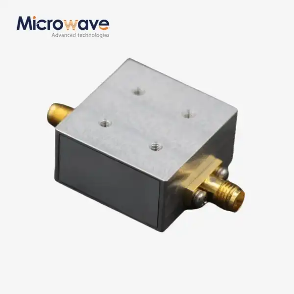
Microwave Fixed Attenuators lower the signal's intensity by a set number of decibels that doesn't change. These devices, unlike variable attenuators, offer constant reduction across their operating frequency range. This makes them perfect for uses that need stable performance. These parts are used in many parts of communication infrastructure, like checking base stations, protecting spectrum analyzers, and setting the sensitivity of receivers. Microwave fixed attenuators are used in defense radar systems to keep amplifiers from getting too hot, and they are also used in satellite uplink facilities to match the output levels of transmitters with the needs of antenna feeds.
Core Function in High-Frequency Systems
Through resistance parts, microwave fixed attenuators get rid of extra power as heat. Thin-film or thick-film resistor networks set up in T-pad, Pi-pad, or bridged-T topologies are often used in their construction. These designs keep the impedance steady (usually 50 ohms) while weakening the signal. This stops reflections that could mess up readings or hurt sensitive parts. The power number tells you how much energy the resistive parts can turn into heat without going over the safe working temperatures.
Essential Technical Parameters Beyond Power Rating
The operating bandwidth is based on the frequency range. Modern systems can handle frequencies from DC to 110 GHz. Insertion loss is the real attenuation value, with standard errors of ±0.5 dB to ±1.5 dB. The Voltage Standing Wave Ratio (VSWR) shows how well the impedance matches. Lower values (1.2:1 or better) mean better performance. Return loss measures reflected power, and numbers above 20 dB are thought to be good. The temperature coefficient shows how stable attenuation is when the environment changes. This is very important for outdoor setups and aircraft uses where the environment changes a lot.
Interpreting Datasheets for Procurement Decisions
The procurement engineers should check to see if the power numbers show the maximum or normal amount of power that can be handled. For continuous-wave signals like carrier transmissions, average power handling is important. For pulsed radar applications, peak power specifications are important. Temperature derating curves show how power capacity goes down when the outside temperature gets higher. Mean Time Between Failures (MTBF) and other reliability data help estimate lifecycle costs. Marks like ISO 9001 and RoHS compliance show that a company cares about quality and the environment. These are important things that, in our 20 years of experience at ADM, we've learned are necessary for building long-term relationships with suppliers.
Critical Factors Affecting Fixed Attenuator Power Rating in Microwave Design
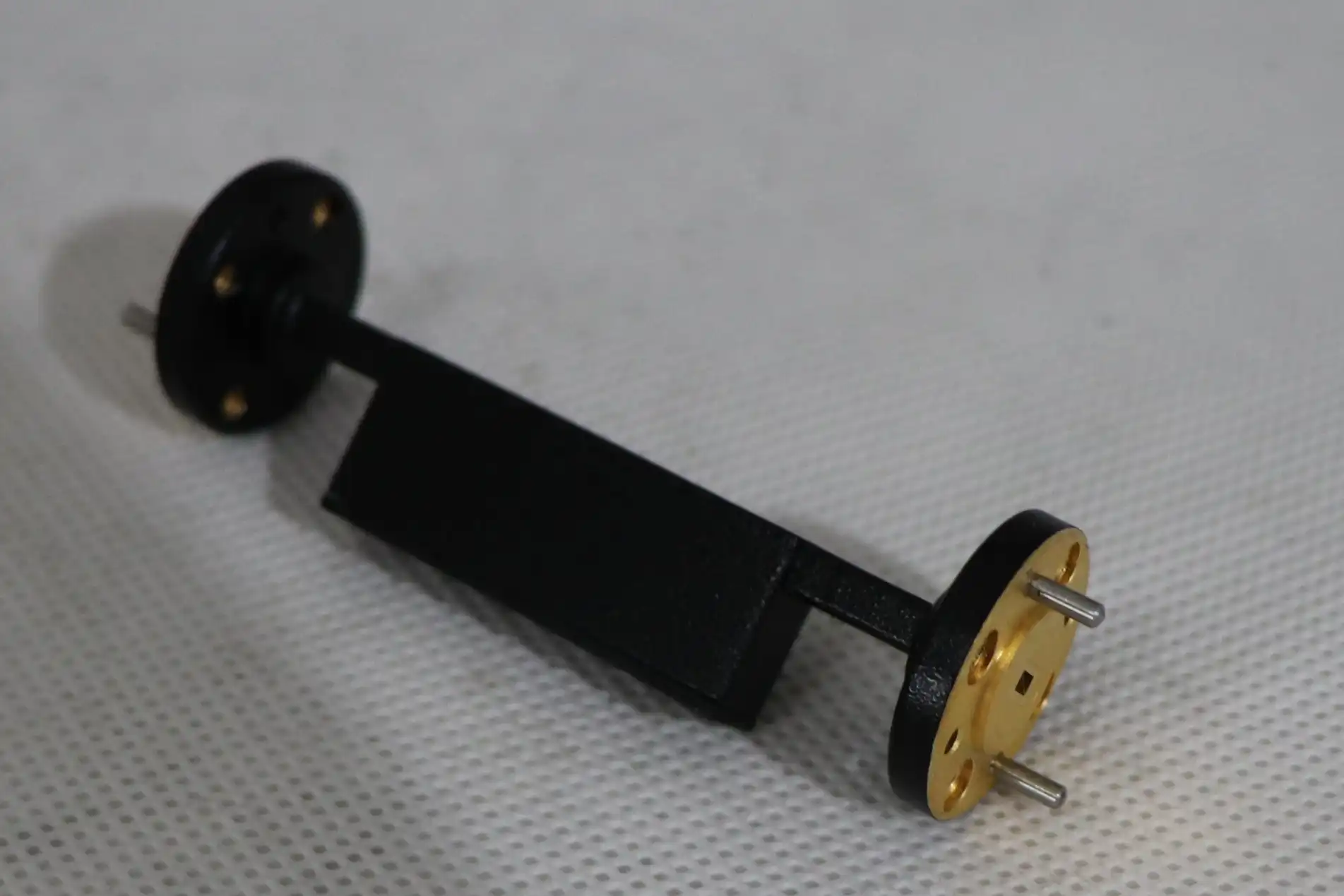
The amount of power a microwave fixed attenuator can handle is determined by a number of related factors. The material of the resistor base, its size, the type of connection it has, and how it cools all affect its thermal performance. When engineers know about these things, they can choose devices that will work reliably in real-world situations, not just in labs.
Power Handling Capacity and Device Categories
Standard power attenuators can handle between 0.5 and 2 watts of power constantly, making them good for measuring tools and low-power transceivers. Medium-power devices can handle 5 to 25 watts and are used for testing base stations and moderate amplifier chains. High-power attenuators can handle 50 to 500 watts or more, which makes them necessary for military radar systems, radio transmitters, and industrial RF heaters. For pulsed systems, where energy spikes happen quickly and are much higher than normal levels, peak power ratings are important. A radar transmitter that sends out 10-kilowatt pulses with a 1% duty cycle averages 100 watts, but it needs attenuators rated for peak power handling to make it through the leading edges of the pulses without arcing or thermal shock.
Thermal Management Strategies
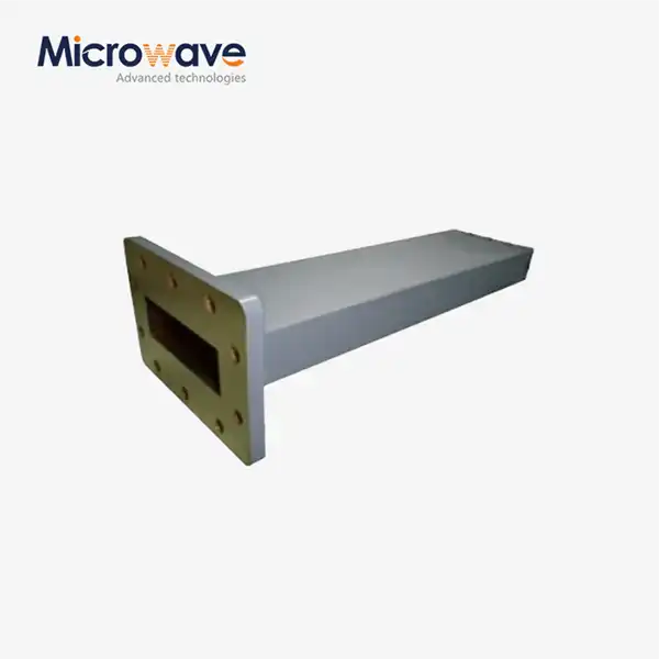
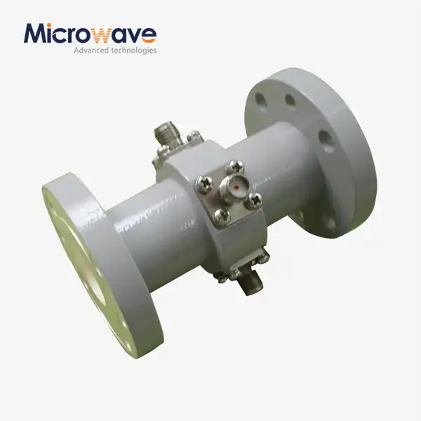
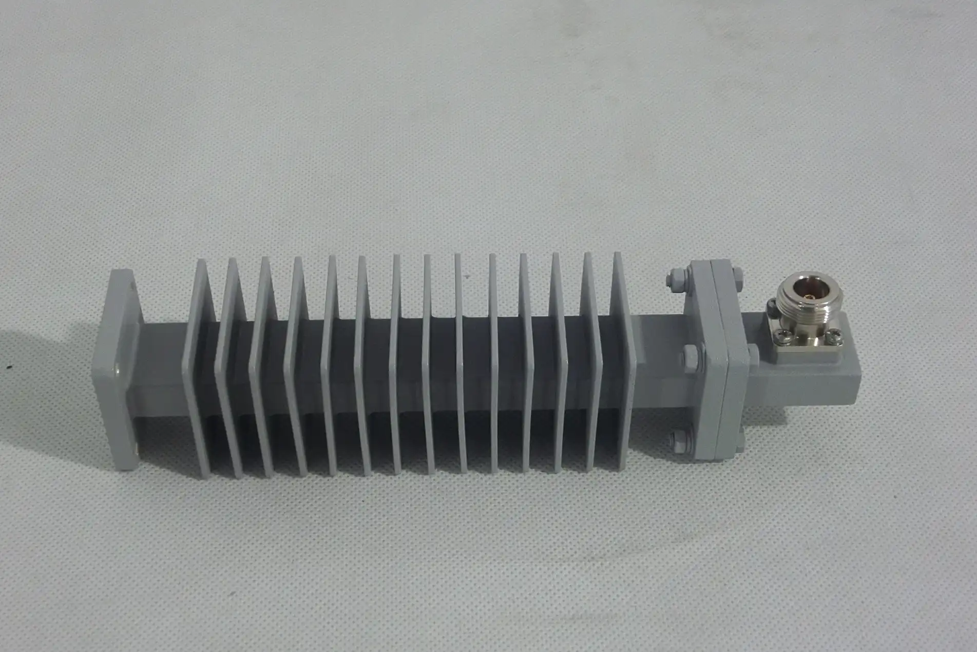
Long-term success depends on how well heat is removed. Microwave fixed attenuators that are mounted on a chassis send heat to heat sinks or equipment cases through mounting flanges. Large surface areas on waveguide attenuators make them good at radiating heat. When there is a lot of power, coaxial systems with small connections put a lot of thermal load on a small area, so they need active cooling. When you measure thermal resistance in degrees Celsius per watt, you can see how much the temperature rises above room temperature for every watt that is lost. Lowering thermal resistance makes parts last longer. For example, Arrhenius dependability models show that a junction temperature of 50°C doubles the device's lifespan compared to 100°C operation.
Frequency-Dependent Performance Variations
Both the power rating and the accuracy of the attenuation change with frequency. At higher frequencies, the skin effect concentrates current in the top layers of the resistor, which raises the resistance and causes the area to heat up. Changes in resistance that depend on frequency are caused by parasitic capacitance and inductance. These changes affect VSWR and return loss. Well-designed attenuators keep the level of attenuation flat within ±0.5 dB across the band they are supposed to work with. Power derating at high and low frequencies stops resonant effects that could cause hot spots in certain areas. Our lab tools that can measure up to 110 GHz show these small changes in performance that aren't always shown in datasheets.
Comparing Fixed Attenuators: Making the Right Power Rating Choice
To choose the right type of microwave fixed attenuator, you have to match its electrical properties to the needs of the application. Fixed, variable, and step attenuators all have their own benefits that rely on the system's design and working needs.
Fixed versus Variable and Step Attenuators
Microwave Fixed Attenuators offer constant reduction and can handle the most power for their size and price. Their simple design, which uses passive resistor networks instead of control circuitry, cuts down on failure modes and raises reliability. Variable attenuators let you make changes in real time by rotating mechanically or controlling the voltage electronically. This is helpful for systems that automatically adjust the strength and adapt to new situations. However, their complexity makes them less powerful and increases the chance of control signal confusion. Step attenuators use switched fixed elements to make discrete attenuation levels. They do this by balancing freedom with power handling. This is common in test equipment where programmable levels are more important than constant change.
Tolerance Impact on System Performance
Measurement accuracy and signal chain gain distribution are both affected by attenuation tolerance in a direct way. In some cases, a tolerance of ±1 dB might be fine for RF power levelling where a close reduction is enough. For precise tasks like measuring antenna patterns or figuring out what an amplifier is made of, tolerances of ±0.25 dB or less are needed. Designs that are stable at temperatures ranging from -55°C to +125°C meet the requirements for military and space qualification. To understand how tolerance builds up across cascaded attenuators, you need to use statistics. For example, three 10 dB attenuators with a tolerance of ±0.5 dB make a total error of about ±0.87 dB when you use root-sum-square calculations.
Selecting Devices for 5 GHz and Beyond
When the frequency goes up, problems like smaller wavelengths, higher connection losses, and stricter impedance control come up. Well-known companies like Mini-Circuits have large catalogs with performance data for millimeter-wave bands that have been checked. When project deadlines are tight, Pasternack's quick-ship options can help. Our experience with satellite communication and radar programs has taught us that the name of the provider is important. Test data that is well-documented, quick technical support, and consistent manufacturing quality all help to avoid failures in the field that could hurt the project's success and people's professional reputations.
Procurement Considerations: Sourcing Microwave Fixed Attenuators with Appropriate Power Ratings
Strategic procurement looks at both technical needs and business realities, like price, availability, and the skills of the supplier. Purchasing managers can get the best results and the best value for their money by understanding how power rating specs affect these factors when sourcing a microwave fixed attenuator.
Specification Impact on Lead Times and Stock
Standard catalogue items with typical power levels (1W, 2W, and 10W) can be shipped within days from stock at the wholesaler. Custom power needs that go beyond what's in the catalogue require engineering design cycles, prototype validation, and production setup, all of which could add weeks or months to delivery times. Keeping a strategic inventory of critical attenuators, including Microwave Fixed Attenuator, on hand helps keep project delays to a minimum, but it uses up working capital. A lot of the time, promises to buy in bulk lead to better prices and sure allocation during times when supplies are low. ADM's OEM services support quick development, which lets you test your idea before committing to large-scale production.
Evaluating Supplier Qualifications
Ask for full datasheets that show the power level for each frequency range and temperature. Check the testing methods—some providers give theoretical calculations instead of actual results that have been tested. Certifications like ISO 9001 show that quality control methods lower the number of mistakes. RoHS compliance protects the environment and allows people to enter markets in areas that are controlled. Ask about traceability—can the supplier show what the material is made of, when it was made, and the test results for each serial number? This paperwork is very important for aircraft and defense uses that need to look into failures and check the supply chain. Response time for technical support often shows how well a company will be able to solve problems in the future. Companies that offer application engineering help are more valuable than just selling parts.
Balancing Cost Against Performance
The cost of materials and labour goes up as the power level goes up. An attenuator for 50 watts usually costs a lot more than one for 2 watts that has the same electrical properties. It's safer to overrate the power rating, but it wastes money. Both under-specification fails and over-specification costs can be avoided with accurate power analysis. Think about the total cost of ownership, which includes the effects of any failures. For example, a $500 attenuator that protects a $50,000 amplifier is like sound insurance. Our low prices at ADM come from 20 years of experience in combined production and efficient supply chain management. We offer professional-grade parts without the high prices of luxury brands.
Best Practices for Installing and Using Microwave Fixed Attenuators at Rated Power
When you install and use a microwave fixed attenuator correctly, it lasts longer, and the system is more reliable. By following the manufacturer's instructions, you can avoid common failure modes that hurt performance and pose safety risks.
Mounting Techniques and Heat Dissipation
For chassis-mount attenuators to work, they need to be in direct thermal contact with metal casings or heat sinks. To keep the contact resistance between the fitting flange and the frame as low as possible, use thermal interface material. As stated, torque connectors to the specified values. Not tightening them enough leads to connections that don't work all the time and higher contact resistance, which creates more heat. Tightening them too much damages the threads on the connectors and squeezes the dielectric materials. Make sure there is enough airflow around the coaxial attenuators and stay away from spaces that are too small and will trap heat. Waveguide attenuators work better when they are positioned vertically, which encourages natural airflow. Never run attenuators at more than 80% of their rated power for long amounts of time. Derating increases their useful life and keeps the accuracy of their tuning.
Calibration and Performance Verification
Before they are installed, new microwave fixed attenuators should be put through baseline tests. Using certified network analyzers, you can measure the real loss, VSWR, and frequency response. Keep track of the results so you can use them to fix problems in the future. Periodic verification finds damage that is happening over time because of changes in temperature or moisture getting in. When you compare measures to the standard data, attenuation changes greater than ±0.3 dB or VSWR degradation beyond what is expected are signs that problems are getting worse. Moisture contamination or resistor damage can be found by measuring the resistance between the center conductor and ground. Thermal imaging during operation shows hot spots that could be signs of problems with the making or installation.
Avoiding Common Power Rating Mistakes
For pulsed applications, you need to know about peak-to-average power ratio and duty cycle. A Microwave Fixed Attenuator must be selected carefully because if you run 100 watts through a 10-watt average attenuator, it might break, even if the average power stays within the limits. When impedances don't match, standing waves happen that cause voltage and current peaks that are higher than normal. This lowers the power capacity. Harmonic content in boosted signals adds power above and beyond the measurement of basic frequency. Extreme temperatures make it harder to handle power; check derating models for real-world working conditions. As resistance elements oxidize and solder joints wear out, power capacity slowly decreases with age. Critical applications need to be replaced on a regular basis, even if they seem to be working fine.
Conclusion
It is very important to know the power ratings of microwave fixed attenuators when choosing them for tough jobs. These parts keep expensive technology safe, allow accurate readings, and keep the integrity of signals in radar, transmission, and satellite systems. To do a good job of buying, you need to compare the power handling to the thermal management, frequency response, and tolerance requirements. When you compare fixed and variable attenuators, you can see that ease and freedom are not always the same. By looking at datasheets, certifications, and expert help, you can tell the difference between trusted partners and commodity sellers. Installing and maintaining parts correctly can make them last longer and keep them from breaking down, which could threaten the mission's success. With 20 years of experience making things, ADM gives defense, aerospace, and telecom workers the accuracy and dependability they need for important microwave uses.
FAQ
1. How do I determine the right power rating for my application?
Find the highest amounts of constant and peak power at the microwave fixed attenuator. Add 30 to 50 percent more to the calculated values as a safety margin. Think about the weather outside and how the shelter will heat up. Instead of time-averaged power, pulsed systems need peak power ratings that match the levels at any given time. When you talk to experienced providers, you can check against similar apps that have already been used successfully.
2. What risks come with insufficient power ratings?
When attenuators don't have enough power, they get too hot and fail right away because the resistors burn out or the solder joints melt. Gradual decline changes attenuation values so they are not in line with what is expected, which makes the system less accurate. Thermal stress speeds up ageing, which lowers service life even if nothing catastrophic happens. Arcing in high-voltage RF settings can damage things permanently and pose a safety risk.
3. How do fixed and programmable attenuator power ratings differ?
Fixed attenuators can usually handle more power because their passive design is easier and there are fewer ways for them to fail. Programmable attenuators have switching parts and control circuitry that limit the amount of heat they can hold. Resistive films can handle more power than PIN diode switches and FET elements. Fixed attenuators with external switching matrices are often used in situations that need both high power and the ability to be programmed.
Partner with ADM for Reliable Microwave Fixed Attenuator Solutions.
The people at ADM have been making precise microwave parts for defence, aircraft, and satellite transmission systems for more than 20 years. As an established microwave fixed attenuator supplier, we provide customized solutions engineered to your exact power rating requirements, backed by ISO 9001:2008 certification and RoHS compliance. Our advanced laboratories, equipped with measurement capabilities extending to 110 GHz, ensure every component meets rigorous specifications before shipment. We offer quick prototypes, low prices through integrated production, and helpful technical support that understands your application challenges. Contact craig@admicrowave.com today to discuss your project requirements and discover how our engineering team can deliver reliable attenuators that improve system performance while staying within tight budgets and time frames.
References
1. Collin, Robert E. Foundations for Microwave Engineering, Second Edition. IEEE Press, 2001.
2. Pozar, David M. Microwave Engineering, Fourth Edition. Wiley, 2011.
3. Rizzi, Peter A. Microwave Engineering: Passive Circuits. Prentice Hall, 1988.
4. Vendelin, George D., et al. Microwave Circuit Design Using Linear and Nonlinear Techniques, Second Edition. Wiley, 2005.
5. Harvey, A.F. Microwave Engineering. Academic Press, 1963.
6. Baden Fuller, A.J. Microwaves: An Introduction to Microwave Theory and Techniques, Third Edition. Pergamon Press, 1990.