Choosing Low Insertion Loss Isolators for Precision Applications
When designing mission-critical RF and microwave systems—whether for satellite uplinks, radar transmitters, or high-frequency test equipment—protecting sensitive components from reflected power is paramount. Low insertion loss isolators serve as the first line of defense, ensuring signal paths remain clean while safeguarding amplifiers, oscillators, and transmitters from damaging reverse signals. These passive ferrite devices allow forward signal propagation with minimal attenuation (typically under 0.5 dB) while blocking reflected energy, making them indispensable for maintaining signal fidelity and system longevity across defense, aerospace, telecommunications, and research environments.
Understanding Low Insertion Loss Isolators: Core Concepts and Benefits
What Insertion Loss Really Means in RF Systems
Insertion loss is a way to measure how much power is lost when a signal goes through a component. In isolators, this parameter has a direct effect on how well the whole system works. A device with 0.3 dB insertion loss keeps about 93% of the input power, while a device with 1.0 dB insertion loss only keeps 79%. Even small changes in decibel levels can save a lot of power and make thermal management easier for high-power devices that work at kilowatt levels.
How Ferrite Isolators Minimize Signal Degradation
Isolators use the non-reciprocal qualities of magnetic ferrite materials that are magnetic. The ferrite junction is biased by a permanent magnet inside, which creates a Faraday rotation effect that lets forward signals travel while absorbing backward signals into a matching resistive load. The shape and quality of the ferrite material decide how much insertion loss there is. Modern industrial methods, such as precise cutting and temperature-compensated magnet systems, can get insertion losses below 0.4 dB across octave bandwidths. This is a big improvement over older designs, which had insertion losses between 0.8 and 1.2 dB.
Key Technical Specifications Beyond Insertion Loss
Even tho insertion loss gets most of the attention, three other factors also affect how well an isolator works. The value of isolation, which measures reverse rejection, is usually between 18 and 25 dB. Higher isolation saves sensitive sources, but it often means more insertion loss. VSWR, or Voltage Standing Wave Ratio, shows how well the impedance matches. Values below 1.25:1 mean that there aren't many echoes at the contact points. Frequency range determines operational bandwidth. Broadband units that cover 2–18 GHz are good for a wide range of uses, while narrowband designs, like those that work best with 13.75–14.5 GHz for Ku-band satellite uplinks, are better for specific channels.
Isolators Versus Circulators: Function and Use Case Distinctions
Even tho both systems use ferrite joints, they are built in very different ways. A low insertion loss isolator stops reverse power from going into a load inside the device. This makes it perfect for protecting the source in signal chains that only go in one way. In diplexer setups, a circulator sends and receives signals in a certain order between three or more ports. This lets multiple functions work at the same time. When purchasing engineers are looking at different parts, they should put isolators at the top of the list to protect amplifiers or oscillators from changes in load, and they should save circulators for situations where two antennas need to be shared and two-way isolation between the Tx and Rx paths is needed.
How to Choose the Right Low Insertion Loss Isolator: Criteria and Decision Factors
Aligning Frequency Range with Application Requirements
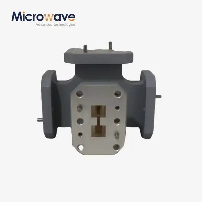
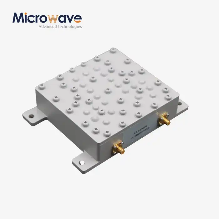
The working frequency of the system determines which isolator to use. For satellite ground terminals to work in the C-band (3.7–4.2 GHz downlink, 5.925–6.425 GHz uplink), they need two separate setups that are tuned to each segment. On the other hand, radar systems that use X-band (8–12 GHz) need broadband isolators that can handle frequency-agile waveforms. Waveguide isolators work great in high-power radar, and SATCOM uses above 10 GHz because they can handle more than 100 watts of continuous power. Coaxial isolators work well with commercial wireless and test equipment that operates below 6 GHz. Their small size and SMA/N-type connections make them easier to integrate.
Performance Trade-Offs: Insertion Loss Versus Isolation
In physics, there are natural trade-offs between reverse isolation and insertion loss. To get isolation levels above 22 dB, you usually need thicker ferrite sections or more junction stages, which raises forward loss by 0.1 to 0.2 dB over time. When buying something, people should think about how vulnerable the system is to mirrored power and how efficient they want it to be. Solid-state power amplifiers (SSPAs) with strong safety circuits can handle 20 dB isolation, with 0.3 dB insertion loss being the most important thing to get the most power out. On the other hand, sensitive frequency synthesizers that drive high-Q filters need 25 dB separation, even if insertion loss is only 0.6 dB. This is so that phase noise degradation from load pulling doesn't happen.
Evaluating VSWR for System Impedance Matching
VSWR less than 1.20:1 across the working range makes sure that there are smooth impedance changes between isolators and nearby parts. When VSWR is low, it changes the frequency response of the system and creates standing waves that raise peak voltages. In high-power situations, this can cause the insulator to break down. Matching limits get tighter when isolators are added to cascaded amplifier chains or filter networks. VSWR below 1.15:1 stops cumulative mismatch loss from reducing link budgets in multi-stage designs.
Procurement Considerations: Customization and Supply Chain Factors
In addition to electrical specs, B2B buyers need to know how well a provider can handle customization, wait times, and quality control. Custom designs for isolators that work with non-standard frequencies, waveguide flanges (like CPR or UG types), or weather sealing (MIL-DTL-85 compliance for salt-fog protection) can make development take up to 12 weeks longer. System integrators can get their products to market faster when they work with suppliers who offer OEM services and rapid prototyping. Certifications like ISO 9001 and RoHS compliance make sure that products can be tracked and meet regulations. This is very important for defense companies who have to deal with ITAR rules and aircraft OEMs who have to follow AS9100 standards.
Pricing systems that are clear are just as important. Pricing based on volume for orders over 50 units can cut costs per unit by 15–25%, which makes buying in bulk a good option for production runs. Delivery reliability affects program plans; providers who keep standard models in stock usually ship them within one to two weeks, but fully customized units may take ten to fourteen weeks, which includes quality testing.
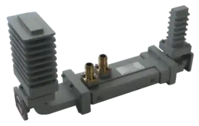
Practical Applications and Case Studies of Low Insertion Loss Isolators
Satellite Ground Stations: Protecting Block Upconverters
High-power amplifiers (HPAs) that make 10–200 watts are used by satellite ground stations that send signals at Ku-band (14–14.5 GHz). The impedance of an antenna changes depending on how it is pointed and the weather. This causes reflected power spikes that can hurt HPA output stages. These reflections are taken in by a waveguide low insertion loss isolator with 0.4 dB insertion loss and 22 dB isolation that is placed between the antenna feed and the HPA. Comparing how well the system worked before and after adding the isolator showed that there were 35% fewer HPA faults and 0.2 dB more effective isotropic radiated power (EIRP) during rain fade.
Aerospace Radar: Stabilizing Transmitter Output
Temperature changes from -40°C to +70°C and shaking levels above 10G are some of the harsh conditions that X-band (9.3–9.5 GHz) weather radar systems have to work in. In their solid-state transmission units, a major defense contractor built in coaxial isolators with an average power rating of 50 watts. The temperature-compensated ferrite junctions in the isolators kept the insertion loss below 0.5 dB throughout the working range. At 20 dB isolation, changes in the load couldn't affect the amplifier's gain or phase. In flight tests, the mean time between failures (MTBF) was 40% longer than in setups that weren't secured.
Wireless Infrastructure: Enhancing Base Station Efficiency
5G macro cell base stations that work in the C-band (3.3–3.8 GHz) use huge MIMO antenna arrays with as many as 64 transmit chains. Each power amplifier sends a specific radio element thru an isolator that keeps radiators next to each other from interacting with each other. Coaxial isolators with an insertion loss of 0.35 dB and a VSWR of 1.20:1 kept transmitted power budgets the same and kept inter-element isolation above 18 dB. The amount of power used per site dropped by 12%, which meant that network operators saved $3,500 per installation per year across 10,000 installs.
Laboratory Test Setups: Enabling Accurate Measurements
When studying low-noise amplifiers (LNAs), research groups need stable source conditions to separate the performance of the device being tested (DUT) from measurement errors. When you put an isolator between the signal generator and the DUT, it takes in changes in impedance that are caused by changes in bias or input mismatch. A university lab that was studying cryogenic LNAs at 4 GHz found that adding a 0.4 dB isolator cut measurement error from ±0.8 dB to ±0.3 dB, which made it possible to accurately describe noise figures below 0.5 dB.
These real-world examples show that isolators have measured benefits, such as making components last longer, using less power, and improving the accuracy of measurements. When you install something correctly, like controlling the torque on coaxial connectors (8–10 in-lbs for SMA) and making sure the flanges on different types of waveguides are lined up correctly, it will work as expected for a long time. Long-term dependability is maintained by checking regularly for ferrite demagnetization (shown by rising insertion loss) and connector wear.
Why Choose ADM for Low Insertion Loss Isolators
Deep Technical Expertise Across Two Decades
Advanced Microwave Technologies Co., Ltd. (ADM) has been making precise RF and microwave passive parts for more than 20 years. Our engineering team has advanced degrees in electromagnetics and ferrite device design. They use their academic knowledge to make isolator solutions that work for frequencies from 500 MHz to 110 GHz. Because we know so much about isolators, we can tell you which ones will work best for your needs, whether they are waveguide units for 40 GHz satellite gateways or coaxial designs for L-band telemetry links.
Comprehensive Testing and Quality Assurance
Our labs have cutting-edge network analyzers that are calibrated to NIST standards. This lets us measure insertion loss with an accuracy of ±0.05 dB. The 24-meter anechoic room lets antenna-mounted isolators be fully characterized while they are in use, proving their performance in real electromagnetic settings. Every step of the production process is governed by ISO 9001:2015 certification, from checking the ferrite material to doing the final electrical tests. This makes sure that the quality of each batch of products is the same. RoHS compliance ensures that global markets are responsible for the Earth and follow the rules.
Customization Capabilities Tailored to Mission Requirements
Standard catalog isolators work for most uses, but custom solutions are often needed for mission-critical systems. ADM's OEM services can handle unique frequency bands, waveguide flanges that aren't standard (UDR, PDR, or customer-specified), and environmental protection according to MIL-STD-810 for shock, vibration, and temperature changes. Our fast prototyping method makes evaluation units in four weeks, which shortens the time it takes to validate a design. We can make anywhere from 10 to over 1,000 units at a time, and because our supply chain is combined, we can offer better prices.
Global Logistics and Responsive Support
Logistics that can change quickly are needed to serve defense contractors, satellite operators, and telecom infrastructure providers all over the world. ADM keeps high-demand isolator types in stock, so urgent needs can be met in one to two weeks. Our export team handles customs paperwork and ITAR compliance for international shipments, making sure that aerospace and defense customers get their orders on time. After delivery, our technical support team helps with installation, fixing, and application engineering. They do this by building relationships that go beyond transactions.
Conclusion
To choose the right low insertion loss isolator, you need to carefully look at the electrical requirements, the environment, and the supplier's abilities. Insertion loss, isolation, VSWR, and frequency range must all match the needs of the system, finding a balance between safety levels and effectiveness. To lower supply chain risks, procurement experts should look at customization choices, wait times, and quality certifications. The given case studies show real improvements in performance, ranging from fewer amplifier failures in military radar to more accurate measurements in the lab. ADM is ready to use our technical know-how, state-of-the-art test facilities, and flexible manufacturing to provide you with isolator solutions that protect your important RF infrastructure. Choosing the right parts today means that the system will work reliably tomorrow.
FAQ
What lead times should we expect for custom isolator designs?
Catalog isolators that are standard will ship within one to two weeks from stock. Prototypes for custom designs that need special frequency bands, waveguide flanges, or sealing against the environment usually take 4 to 6 weeks to arrive. Depending on the number of items ordered, volume production runs take an extra 6 to 8 weeks. During the quotation phase, ADM's engineering team gives detailed project timelines that take into account getting materials and qualifying tests to make sure that delivery promises are realistic.
How does insertion loss impact overall system performance?
About 2.3% less signal power is available for every 0.1 dB of insertion loss. A 0.5 dB isolator splits 11 watts into heat and forward flows 89 watts in a 100-watt emitter chain. Multiple lossy components cascading through a link drain its budget—three steps at 0.5 dB each use 1.5 dB total, which is 30% less power. Keeping insertion loss as low as possible protects radiated power, lowers the need for cooling, and increases the operational margins of an amplifier.
Can isolators handle high-power pulse radar applications?
Average (CW) ratings are not the same as peak power usage scores. Waveguide isolators that are rated for 200 watts CW can usually handle 5 to 10 kW of peak power at 10% duty cycle. The thermal time constant of the ferrite junction lets short pulses of high power pass through it without damaging it, as long as the average dissipation stays within limits. For pulse radar uses, you need to check both the peak and average power specs. To keep you from applying the wrong parameters, ADM's datasheets make these specifications very clear.
Are broadband isolators suitable for frequency-hopping systems?
Broadband isolators with octave bandwidths, like 2-4 GHz or 8-18 GHz, can handle frequency-agile patterns that are widespread in electronic warfare and military communications. Insertion loss flatness, or change across the band, affects how well hopping works. Specifications that are tighter than ±0.3 dB make sure that link margins are the same on all channels. When set to certain frequencies, narrowband designs have lower absolute insertion loss, but they aren't flexible enough for systems that change quickly.
Partner with ADM for Superior Isolator Solutions
Picking a trustworthy low insertion loss isolator provider means picking a partner who gets your technical problems and offers tried-and-true answers. ADM has decades of experience in RF engineering, ISO-certified manufacturing, and full testing capabilities up to 110 GHz. Our team can help you with everything from reviewing specifications to mass production of waveguide isolators for defense radar projects, cable units for telecom base stations, or custom OEM designs for satellite ground terminals. Email our engineering team at craig@admicrowave.com to talk about your needs, get detailed datasheets, or get quotes for both prototypes and production quantities. As a reliable low insertion loss isolator manufacturer with users in aircraft, defense, and telecommunications around the world, we can help you improve the performance of your RF signal chain with high-quality parts that will last for a long time and work well.
References
1. Helszajn, J. (2018). Ferrite Phase Shifters and Control Devices. Institution of Engineering and Technology Press.
2. Pozar, D. M. (2021). Microwave Engineering, 5th Edition. Wiley Publishing.
3. Baden Fuller, A. J. (2017). Ferrites at Microwave Frequencies. IEEE Magnetics Society Monograph Series.
4. Collins, R. E. (2019). Foundations for Microwave Engineering, 3rd Edition. McGraw-Hill Education.
5. Ishii, T. K. (2020). Handbook of Microwave Technology: Components and Devices, Volume 1. Academic Press.
6. Gardiol, F. E. (2016). Microwave Passive Devices and Applications. Artech House Publishers.