




Cassegrain Antenna Design Guide for Satellite Ground Stations
A cassegrain antenna has two reflectors: a large parabolic dish and a smaller hyperbolic subreflector. For satellite ground stations that need high gain, low noise, and easy access to RF gear, it works well. The first parts of a good design are the goal, the frequency range, and the link budget. After that, you match the reflector's shape, feed type, surface accuracy, and alignment limits. You can tell how the design works, how well it works, what your options are, and how to buy with confidence by reading this guide. This way, your team can write a clear brief before you ask for quotes.
Understanding the Cassegrain Antenna Structure
What Is a Cassegrain Antenna?
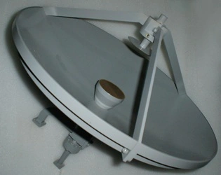
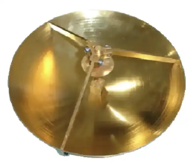
If you have a parabolic antenna and two reflectors, you have a cassegrain antenna. Some of the things that make it up are an RF interface, a feed system, a support structure, and a primary reflector. In 1672, Laurent Cassegrain made a telescope with a similar two-mirror design. This is where the style got its name. The feed turns on the subreflector when it's time to send, and it sends the energy to the primary reflector. The dish then sends a narrow beam to the satellite. It works the other way around for reception. That's what I call a "folded optical path." The subreflector keeps the structure small while making the effective focal length long. It has a high gain even though it doesn't have a deep dish or a long feed boom.
Where the Feed and Electronics Sit
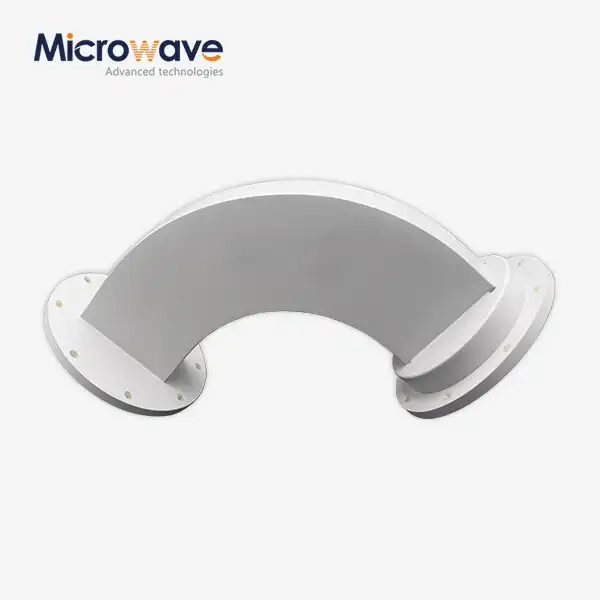
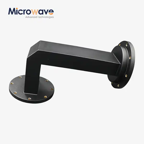
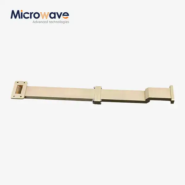
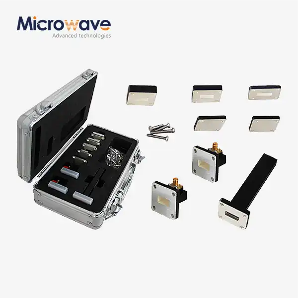
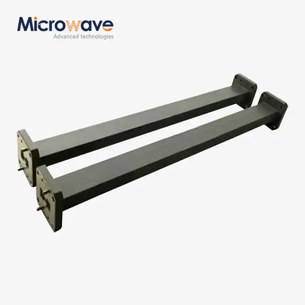
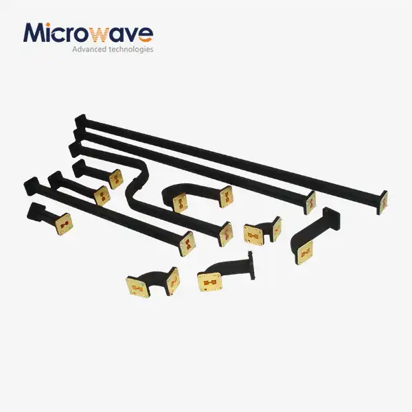
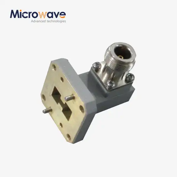
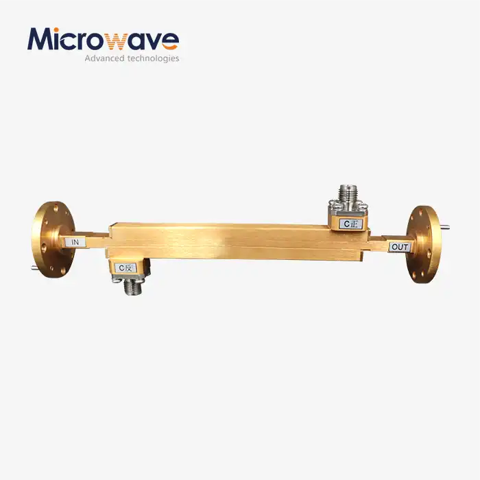
It's folded so the feed is close to the edge of the reflector and behind the main dish. It cuts the waveguide run between the feed and the low-noise amplifier or converter short at that point. This makes the insertion loss less. It is very important to have short runs with Ku-band and Ka-band because the receive noise is very low. The receive noise figure changes by a small amount for every decibel. They can also get to amplifiers, converters, and dual-polarized RF gear more easily when they are not hanging at the focal point but rather near the rear hub. For service teams to work on them, they don't have to be moved to a feed support at the front of the dish. As an ADM company, we sell waveguide assemblies, coaxial and cable assemblies, as well as the feed parts that connect this gear to the antenna.
Why Focal-Point Accuracy Matters
The subreflector and the feed alignment determine how well the antenna forms its beam. If the subreflector isn't in the right place, the feed will light up the main dish in an uneven way. It's possible for that mistake to lower the gain, widen the beam, add sidelobes, taint the polarization, and change how well the device works across frequencies. Often, beam squint is caused by the feed or subreflector not being lined up correctly. Beam squint is a small difference between the expected and actual beam direction. The main reflector's surface error should usually be kept close to »/20 RMS or better. An GHz wave is about 25 mm long, which means that λ/20 is about 1.25 mm long. At 30 GHz, the rule gets even stricter and ends at about 0.5 mm. I always ask suppliers how they make sure the center of attention is in the right spot when putting the part together.
Cassegrain Antenna Design Principles and Performance
Reflector, Subreflector, and Feed Coordination
When the design of a cassegrain antenna works well, it considers the reflector's shape, the feed, the lighting, the blockage, and the overall manufacturing tolerances. A parabolic curve is often used to shape the main reflector, and a hyperbolic curve is often used to shape the subreflector, which sets the optical path and aperture distribution. Some of the most important parameters are the size of the subreflector, the distance between the vertices, the position of the feed, the aperture diameter, and the accuracy of the surface. The frequency, polarization, impedance, power level, and tracking method must all be the same as the feed. Blockage and spillover can also be managed by designers. When energy doesn't get to the dish, it's called spillover. When energy does get to the dish, it's called blockage. As they move toward the warm ground, these two effects make things less useful, and the noise temperature goes up. I check for blockage first when the aperture is small because it's the most important thing.
Gain, Efficiency, and G/T
G = ·(πD/λ)² is a simple way to find the gain. In this formula, D is the aperture diameter, λ is the wavelength, and η is the overall efficiency. For a 2.4-meter dish at 12 GHz and a 65% efficiency, this is about 47.7 dBi. The real results depend on how well the phase, polarization, reflection, and spillover work. Most designs with two reflectors get between 60% and 70% of the vote. A ground station also keeps an eye on the antenna gain-to-system noise temperature (G/T) ratio because it tells them how sensitive the receive signal is. It's true that bigger apertures make the gain higher and the beam narrower, but they also need stronger structures and better pointing. When someone wants to buy something, I tell them to look at the gain, efficiency, and G/T across the whole frequency range.
Radiation Pattern and Regulatory Compliance
You should look at the main beam gain, beamwidth, sidelobes, cross-polarization, and front-to-back ratio when you look at a pattern. 70°/D is an easy way to find beamwidth. At 12 GHz, this means that the same 2.4-meter dish makes a beam that is about 0.7 degrees wide. A lot of thought goes into making sure the pointing is correct because the beam is so narrow. Sidelobes are important because they stop interference from satellites that are close by. Teams often look at patterns at earth stations and compare them to the design goals in ITU-R S.580. U.S. operators also look at 47 CFR 25.209, which is the FCC's set of performance standards. Cross-polarization changes how frequency reuse works on links with two polarizations. Users of radar and spacecraft both use the same pattern data to control the range of detection and the number of false alarms. I believe you should request both measured and simulated patterns before giving the go-ahead for a design.
Selecting and Comparing a Cassegrain Antenna
Define the Ground Station Mission First
The first thing that is picked is the mission, which could be radar, deep-space communication, radio astronomy, Earth observation, or TT&C. Each mission has its own set of priorities. A telescope must have a high gain and strong polarization isolation in order to handle both Ku-band and Ka-band traffic. A servo that can point straight needs to be in a tracking station. A research lab might need a feed that can be changed and support a number of different frequencies. The next step is to set goals for the frequency band, aperture, gain, G/T, beamwidth, sidelobe limits, polarization, return loss, power handling, environmental ratings, and correct tracking. I've found that writing down the quotes before calling suppliers makes it much easier for teams to compare them.
Cassegrain vs. Prime-Focus, Gregorian, and Horn Antennas
You should compare the cassegrain antenna to other options that use a parabolic reflector to find the best one for your system. With a prime-focus dish, the feed is put in front of the reflector at the center of the dish. That makes the design simple and cheap, but the cables need to be longer, and the support for the feed needs to be stronger. It is easier to get to the rear feed of a cassegrain antenna, and its effective focal length is longer, but it is harder to make and control blockages with them. In Gregorian antennas, there is a subreflector that is concave and placed beyond the focal point. In some ways, they might be better for packing. Horn antennas can be used as separate radiators or as feed elements in reflector systems most of the time. You should think about things like gain, beamwidth, sidelobes, frequency range, mechanical depth, feed integration, how much it costs, how to install it, and how to keep it in good shape.
Balance Size, Site Conditions, and Total Cost
Getting the biggest reflector isn't always the best thing to do. Think about how the antenna will be moved, set up, and taken care of, as well as how much wind it will be exposed to. More dish means more gain, but more dish also means more mass, which makes the mount heavier and the foundation bigger. Think about how much it will cost you to own the RF electronics, the mount, shipping, customs, spare parts, setup, and long-term technical support. The cost of a link budget can go down over time if the aperture is a little smaller and the receive chain has less noise. I think you should run the link budget with realistic margins for rain fade and atmospheric attenuation before you set the diameter. Next, check to see if the foundation and truck plan match the size that was picked.
Cassegrain Antenna Design for X, Ku, Ka, and Millimeter-Wave Bands
X-Band and Ku-Band Requirements
A lot of the time, X-band systems are used for government communications, radar, Earth observation, and testing spacecraft. Strong construction and low sidelobes are very important here because these areas have to deal with bad weather and strict rules about interference all the time. A Ku-band antenna can be used for both fixed earth stations and broadband satellite links. So they can work together; they need to be far apart in the geostationary arc and follow regulatory pattern masks. At these frequencies, the feed, orthomode transducer, and waveguide parts need to keep the return loss low across the whole band. Custom feed networks, waveguide assemblies, and coaxial assemblies are all things that ADM makes. There are also X-band feed networks that they make. These are used in air traffic control radar, defense surveillance systems, and satellite ground stations.
Ka-Band Requirements
This type of radio can send more data, but the antenna has to be able to handle more. Following the ε/20 rule, the surface should be correct to within 0.5 mm RMS at 30 GHz, where the wavelength is about 10 mm. It's important to keep the point stable since the beam is narrower. It's important to keep an eye on the temperature because changes can bend a dish or move the subreflector. Also, rain fade gets worse at Ka-band, so link budgets need more space. The short feed path of a cassegrain antenna is very helpful because waveguide loss goes up with frequency. To keep tolerances small, high-end units often use aluminum reflectors made of carbon fiber or stretch-formed carbon fiber. I believe you should ask for data on the measured accuracy of the surface for each Ka-band design.
Millimeter-Wave Applications
A lot more care needs to be taken when cutting and aligning millimeter-wave antennas. It takes up more of the wavelength when the frequency goes up, and the wavelength gets shorter as the frequency goes up. The surface roughness, coating thickness, subreflector position, and feed alignment of the final pattern are more important things to pay attention to. Some of the things that can be used are high-resolution radar, scientific instruments, sensing, and fast links. Also, it gets harder to check, so the supplier should have tools for measuring that cover the target band. ADM has labs with tools for measuring microwaves that can go up to 110 GHz and a microwave darkroom that is 24 m long and can test frequencies from 0.5 GHz to 110 GHz. At these frequencies, our engineers use it to check patterns, gain, and impedance. They should provide designs made for that band and information on how well they work, no matter what band it is.
Procurement, Installation, and Acceptance Testing
What to Request From a Global Supplier
You need to do more than just compare prices when you buy a cassegrain antenna from other countries. First, you should choose if a standard product meets your needs in terms of mechanical, environmental, frequency, aperture, feed, polarization, and feed. If not, you should make changes. Next, request drawings, measured gain, radiation patterns, beamwidth, sidelobes, cross-polarization, VSWR, surface accuracy, materials, environmental ratings, inspection records, and test reports from the factory that say the product is ready to use. VSWR is usually less than 1.3:1. It's important to find a company that does good design, metrology, RF testing, international shipping, OEM experience, and customer service after the sale. The business terms should include Incoterms, the type of packaging, delivery dates, acceptance criteria, the warranty, spare parts, and who is in charge of technical issues. ADM offers OEM services, quick prototyping, and help for engineers. They follow RoHS rules and have ISO 9001 certification.
Installation and Site Acceptance Testing
How well something works in the real world depends a lot on how well it was installed. Before putting it together, check the size of the foundation, where the anchors are placed, how easy it is to lift, the range of tilt and elevation, where the cables will go, and how wind, snow, earthquakes, and corrosion will affect it. Then, either use beacons, optical tools, or RF measurements to make sure that the feed, primary reflector, and subreflector are all lined up correctly. Last, make sure the encoders and pointing are set correctly. As part of the acceptance process, you should test the gain, beamwidth, sidelobes, cross-polarization, return loss, port isolation, accuracy of pointing, and G/T. If the job is outside, find out if the coating has been tested for ASTM B117 salt spray and if the building can stand up to wind. First, check the mechanical alignment, and then the RF chain; if you see low gain, high sidelobes, bad polarization, or not stable pointing.
A Simple Decision Process for Choosing a High-Gain Antenna
It saves a lot of money for both the engineering and procurement teams when there are gaps in the specifications. The frequency, orbit, link budget, and application are the first things to look at. First, figure out how much gain and aperture you need. Remember to think about path loss, atmospheric attenuation, rain fade, and system margin. Set the minimum requirements for the device's gain, G/T, beamwidth, sidelobes, cross-polarization, VSWR, pointing, and how long it can work in different places. Give each proposal a score based on how well it works, how easily it can be changed, how well it is documented, how long it takes to make, how much it costs to own, its warranty, and its service. Before production begins, make sure that the design has been reviewed, that prototypes meet the requirements, that there are factory acceptance tests and site acceptance tests, and that spare parts can be easily found. This way of comparing keeps things fair, so price is just one of many things that are taken into account.
Conclusion
The light path in a cassegrain antenna is folded by a subreflector. This makes a ground station small, gives it high gain, and lets you get to the feeds and RF electronics from the back. Performance is impacted by things like the shape of the reflectors, the design of the feed, the lack of spillover and blockage, and the accuracy of the surface, which should be close to µ/20 RMS. The design meets the requirements of ITU-R and FCC pattern standards as shown by measurements of gain, G/T, sidelobes, and cross-polarization. When compared to the prime-focus, Gregorian, and horn layouts, the Cassegrain layout makes it easier to get to the gain and feed. As you move from X-band and Ku-band to Ka-band and millimeter-wave, your designs become more accurate. With a clear mission statement, realistic link margins, a total-cost analysis, full documentation from the supplier, careful installation, and acceptance testing against written standards, you can make a good choice.
FAQ
Q1: Why choose a cassegrain antenna over prime focus for Ka-band?
As the frequency goes up, so does the waveguide loss. The feed and receiver of a cassegrain antenna are close to the point. This keeps the waveguide runs short, and in the receive chain, each decibel is important. The runs to the front of the dish need to be longer for prime focus.
Q2: What is the basic gain equation?
G = η(πD/λ)², where η is the total efficiency, D is the circle's diameter, and λ is its wavelength. With a 65% efficiency and a 2.4-meter dish working at 12 GHz, you can get about 47.7 dBi.
Q3: Is it suitable for Ku-band and Ka-band?
Yes. Both bands work as long as the frequency, feed, and surface accuracy are all the same. Tolerances need to be tighter for Ka-band.
Q4: Standard or custom configuration?
It is best to use a standard unit when the needs for frequency, aperture, feed, polarization, and environment are all the same. It is best to use a custom design when the feed interface, tracking mode, or site conditions are different.
Request a Cassegrain Antenna Quotation from ADM
Do you want to build a ground station and need a dependable cassegrain antenna supplier? ADM has strict quality control, quick delivery, and great customer service after the sale. They also do all of their own research and development and production. Craig@admicrowave.com you should send information about your site, frequency, aperture, polarization, and feed interface to Craig@admicrowave.com. Our engineers will take a look at your setup and come up with a quote that fits your needs.
References
1. Balanis, C. A. Antenna Theory: Analysis and Design, 2016.
2. Stutzman, W. L., and Thiele, G. A. Antenna Theory and Design, 2012.
3. Milligan, T. A. Modern Antenna Design, 2005.
4. Ruze, J. Antenna Tolerance Theory: A Review, Proceedings of the IEEE, 1966.
5. ITU-R Recommendation S.580-6, Radiation Diagrams for Use as Design Objectives for Antennas of Earth Stations Operating with Geostationary Satellites, 2004.
6. IEEE Std 145, IEEE Standard for Definitions of Terms for Antennas, 2013.