




Pyramid Antenna Gain Characteristics Engineers Should Know
A pyramid antenna, which is often a pyramidal horn, is used to gain energy by directing it over a wider rectangular aperture. Gain relies on the size of the aperture, the wavelength it operates at, how well it works, the form of the flare, and how well the impedance matches. As the aperture becomes larger or the frequency becomes higher, the gain increases at the same size. But the beam is becoming smaller, and the alignment has to be more precise. Gain should be seen as a curve that varies with frequency. It should be compared to beamwidth, sidelobes, and VSWR. It should be validated using observed data. This guidance was created to assist US engineers and purchasers in considering these issues when choosing or buying a part for a radar, EMC, or communication connection project.
How a Pyramid Antenna Produces Gain
Structure and Operating Mode
The pyramid antenna consists of a square waveguide feed that flares out in the E-plane and in the H-plane to a square aperture. The horn is fixed to the waveguide run using a mounting flange. The progressive flare matches the guided wave to free space. This reduces reflection and produces a main beam with a direction. Most rectangular waveguide horns function in the TE10 mode, and the electric field is linearly polarized throughout the aperture. To me, the flare is like a phase controller. A longer horn flattens the wavefront at the aperture and cleans the pattern. The form of the flare walls is also important.
Gain Versus Directivity
Directivity is the ability of an antenna to focus its power in one direction. Gain is defined as directivity times radiation efficiency, and so includes actual losses. The losses are due to the resistance of the conductor, manufacturing tolerances, and the roughness of the flange interfaces. The realized gain is also reduced by an impedance mismatch. The standard formula is G = 4πAε/λ², where A is the size of the aperture, ε is the efficiency of the aperture, and λ is the wavelength. The gain in dBi is used to measure the antenna against an isotropic radiator. Aperture efficiency, not ohmic loss, is responsible for the majority of the difference between a theoretical and a measured figure. This is because good horns tend to have low conductor loss.
A Worked Gain Estimate
The scale is shown by a simple case. The wavelength is about 3 cm at 10 GHz. A hole 15 cm by 12 cm in size gives you 180 cm². The formula gives a gain of about 126, or about 21 dBi, when the aperture efficiency is set to 0.5, which is a common first-pass value for pyramidal horns. Here are two rules for scaling. It takes about 3 dB more to double the aperture area at the same frequency. When you double the frequency and keep the aperture the same, you gain about 6 dB. This is because gain increases with 1/λ². The numbers are only examples and are not specifics about the product. Use this number as a starting point, and then compare it to what you see in simulations and in real life.
Pyramid Antenna Dimensions, Frequency Coverage, and Radiation Pattern
Aperture, Wavelength, and Flare Geometry
Maximum gain depends on aperture size and wavelength. Dimensions and angle of horn flare determine antenna placement near the ceiling. The feed-to-outside path is longer than the center path if the horn is too short for its aperture. Phase errors diminish efficiency and increase sidelobes. The path difference is limited to ~0.25º in the E-plane and 0.375º in the H-plane. Since even a little interface mismatch may lower gain, waveguide size and flange accuracy are critical. Match the aperture size to the necessity since larger apertures cost more, are heavier, and require more precision aiming.
Gain Across the Operating Band
Due to wavelength fluctuation across the band, gain changes with frequency even with unchanged hardware. Small to medium-range pyramid antennas may provide high gain. Otherwise, bigger designs have more gain, beamwidth, and polarization purity variations. Engineers should distinguish between the recommended operating band, usable VSWR band, calibrated band, and gain-guaranteed band. These ranges are often unclear on datasheets. A horn may be matched at a frequency without supplier gain evaluation. Ask about the gain curve, not just a headline value, and what range each standard covers.
Radiation Pattern Data to Request
Gain alone reveals nothing about a beam. Request E- and H-plane beamwidths, sidelobe levels, front-to-back ratio, and cross-polarization. These parameters control coverage, isolation, and measurement uncertainty. In EMC testing, a narrow beam lights a smaller test region, yet strong sidelobes collect chamber reflections. In radar and link operation, sidelobes affect surrounding emitter interference. Gain is usually higher with a wider beam. An antenna excellent for point-to-point communication may not work well in a vast test zone. You require pattern cuts at several frequencies because the beam shape varies throughout the band.
Calculating, Validating, and Comparing a Pyramid Antenna
From Requirements to First-Pass Dimensions
The frequency range, target gain, beamwidth, polarization, waveguide standard, flange type, size limits, and accuracy of calibration are the first things that are thought about when designing. I figure out the gain formula for the aperture area based on the gain target and an assumed efficiency. Then, I divide the aperture area into E-plane and H-plane dimensions based on the beamwidth need. Very rarely do the two planes need to have the same size. Next, I set the length of the horn so that the phase error stays within the earlier ranges. Higher-order modes, phase error, and machining tolerance all change the outcome, so these first-order results don't tell us what the final performance will be. For me, they're like a design direction that simulations must back up.
Simulation, Prototype, and Measurement
There is a reliable path that goes from analytical sizing to full-wave simulation, then to a prototype and measurement that has been calibrated. It is important to measure things like gain, VSWR, radiation patterns, polarization, sidelobes, and mechanical dimensions. IEEE Std 149 describes the standard ways to test antennas, such as comparing the gain of an antenna to a reference antenna. For this purpose, a standard gain horn is often used. Runs at different frequencies show how the gain changes as you move across the band. Our labs at ADM have measuring tools that can handle frequencies up to 110 GHz, and our 24 m microwave darkroom can handle test frequencies from 0.5 GHz to 110 GHz. We can compare a prototype to its simulated pattern in that range before starting mass production.
Comparison with Other Microwave Antennas
Use, not headline gain, to compare a pyramid antenna to other options. Because of their gain and mechanical shape, standard gain horns are good for reference measurements. Also, the shape of horns is simple, which makes them easy to machine and inspect. Larger electrical apertures in parabolic antennas give them a higher gain, but they need to be aligned more precisely, and their feeds need to be carefully integrated. Log-periodic antennas work with a wider range of frequencies than horn antennas, but their pattern and gain stability are different. Pick one based on its frequency range, beamwidth, need for calibration, measurement distance, portability, polarization, and size. Different groups, such as a lab measuring patterns, a radar team simulating targets, and an OEM building a subsystem, will use these factors in different ways.
Pyramid Antenna Applications and ADM Product Options
EMC, Chamber, and Measurement Use
In anechoic chambers, pattern measurement, gain comparison, radar simulation, and material characterization, pyramid horns are used to test for radiated emissions and immunity. As long as the supplier gives you calibration data, their steady beam and linear polarization make them good for controlled lab work. Horns are also used in directional microwave links when a steady beam is needed. Engineers should also think about where the phase center is, how far away it is, how repeatable the mounting is, and how to line up the polarization. The far-field distance is given by 2D²/λ, where D is the largest aperture dimension. This means that a longer chamber is needed for a bigger aperture. At 10 GHz, a 15 cm aperture needs about 1.5 m already. A small difference in rated gain may not be important if these things are set up wrong.
OEM and Custom Integration
OEM buyers often ask for bands that aren't standard, special flanges, lightweight construction, protective coatings, dual polarization, sealing against the environment, or custom brackets. Sending drawings, tolerances, and inspection standards early on keeps problems with integration from happening during production of prototypes and large quantities. Send the mechanical drawing along with your first question. As an OEM service provider, ADM offers quick prototyping, technical support from our engineers, and efficient production and delivery. Our technical support also includes help with installation and fixing problems. A small R&D team or a large manufacturer can both use a prototype to test a design before ordering a lot of them. Our products are certified by ISO 9001 and RoHS, which helps procurement teams keep track of which suppliers are qualified.
Pyramid Horn Lens Antenna Option
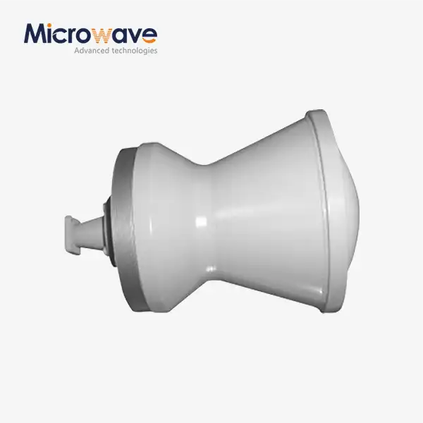
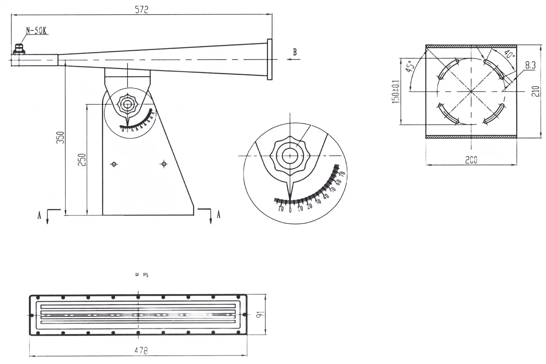
The ADM Pyramid Horn Lens Antenna is a good choice for people who need a shorter horn with a high gain. The aperture or throat of the flare has a dielectric lens that sits there. This lens is usually plano-convex or meniscus, and it fixes the spherical phase error that limits a regular horn. The lens changes the spherical wavefront into a flat one. This lets the antenna reach high gain and low sidelobes in a shorter length. Depending on the model, they usually work from 18 GHz to 110 GHz and have gain levels of 25 to 35 dBi and sidelobe levels better than -25 dB. To keep things working well, lens materials with low loss like PTFE, Rexolite, or TPX are used. Because a dielectric breaks down at a lower temperature than air, power handling needs to be looked at again.
Choosing a Pyramid Antenna Supplier and Avoiding Mistakes
Technical Evidence to Request
Ask for phase center, VSWR or return loss, E- and H-plane patterns, beamwidth, polarization, cross polarization, power management, and frequency-sensitive gain. Then you’ll want to question if each figure is theoretical, average, guaranteed, or your unit. Calibration certifications requested by precision measurement systems and EMC laboratories should provide test technique, traceability, uncertainty, serial number, and results for each individual. The purchasing teams should verify measurements, assist with prototypes, manufacturing capacity, export documentation, packaging, lead time, warranty, and aid with recalibration. An inexpensive but not adequately documented pyramid antenna can cost more to test again. If you have clear answers to these questions, you can compare two apples-to-apples quotations.
Quality Checks for a Lens-Based Horn
The lens introduces a dielectric portion; therefore, it is feasible to test more than the metal body. I look for these three checks:
- VSWR Measurement: A vector network analyzer confirms the match across the whole working range, and a typical target is below 1.5:1. A bad match causes loss of power, changes the realized gain, and adds ripple to measurements. Ask the provider whether they test each item or just a sample, and ask for the measured plots with your purchase.
- Pattern check: Far-field testing in an anechoic chamber validates sidelobe levels and cross-polarization discrimination against the specification, e.g., more than 30 dB of isolation. This check verifies that the lens is correcting phase as specified and that the beam is pointing where the data sheet indicates it should. Request E-plane and H-plane cuts.
- Lens profile and material: Laser scanning measures lens curvature to a tolerance of λ/50 or better, and material inspection guarantees stable dielectric constant and low loss tangent. The impurities absorb the mm-wave energy, which decreases the gain and potentially heats the lens; thus, I want these data as well as the entire metal dimension reports.
These tests seek the main dangers of a lens horn: mismatch, phase error, and material loss.
Common Evaluation Mistakes
When picking an antenna, several errors are made. Buyers don’t believe maximum gain is optimal; therefore, they don’t consider trade-offs such as beamwidth, size, alignment tolerance, and coverage. It is not always evident what the range of the product is when they compare gain values collected at various frequencies. Aperture efficiency, mismatch loss, and the difference between estimated and observed gain are not considered. If the task requires regulation or highly exact work, they will take generic catalog data instead of individual test reports and dimension records. They also do not match aperture size, phase center, and far-field distance while setting up the test. These are very costly errors since they are late in the game, such as during chamber testing or system integration. By not making these errors, you save time and effort re-testing and re-procuring.
Conclusion
Pyramid Gain: The gain of a pyramid antenna depends upon dispersing the steered energy across a rectangular aperture. The size of the aperture, the wavelength, the efficiency of the aperture, the flare shape, and the impedance match all impact the outcome. To double the aperture area requires roughly 3 dB; to double the frequency at a constant size takes about 6 dB. But more gain means a smaller beam and tighter alignment. The engineers should be able to read the gain throughout the whole working band, as well as the VSWR, beamwidth, sidelobes, and cross-polarization. Formulas offer a broad concept; simulations and calibrated measurements verify it. The right horn is also variable depending on whether it is used to compete with a regular gain horn, a parabolic antenna, or a log-periodic antenna. Shorter lengths of lens horns may correct the phase error to provide better gain. Test reports and inspection records indicate the discrepancy between the actual result and the intended outcome.
FAQ
Q1: Why choose a Pyramid Horn Lens Antenna over a standard pyramidal horn?
It has higher gain and lower sidelobes than a standard horn of equal gain because the lens fixes phase errors. The antenna also has a shorter, more compact body. It also keeps the axial length short without lowering the efficiency of the aperture.
Q2: What frequency range do these antennas cover?
If you look at microwave and millimeter waves, the best range for them is between 18 GHz (K-band) and 110 GHz (W-band).
Q3: Does the lens affect power handling?
Yes. Lens dielectrics, like PTFE, break down more slowly than air. The design works well for receiving and testing, but for high-power transmission, thermal analysis is needed to keep the parts from breaking or deforming. Talk to the supplier about power levels before you place an order.
Q4: How does lens material affect performance?
A low loss tangent is found in TPX and Rexolite. Poor materials soak up millimeter-wave energy, which lowers gain and can heat things up.
Request a Pyramid Antenna Quote from ADM
ADM can help you go from a goal to gain to a part that has been tested. We can quickly meet your needs as a pyramid antenna manufacturer with ISO 9001 certification, RoHS-compliant products, a 24 m microwave darkroom, and support for OEM prototyping. Send your frequency band, target gain, interface, polarization, quantity, and destination to craig@admicrowave.com. Our engineers will look over your needs and get back to you with a clear technical proposal.
References
1. Antenna Theory: Analysis and Design, 2016
2. IEEE Standard Test Procedures for Antennas (IEEE Std 149), 1979
3. Microwave Engineering, 2011
4. Antenna Engineering Handbook, 2007
5. Electromagnetic Horn Antennas, 1976
6. Antenna Theory and Design, 2012