Can a Waveguide Low Pass Filter Hit 100 dB Stopband Attenuation?
A waveguide low pass filter can achieve 100 dB stopband attenuation, but only under specific design and manufacturing conditions. Standard commercial filters typically deliver 60–80 dB rejection. Reaching 100 dB requires precision-machined waveguide structures (such as waffle-iron or corrugated topologies), high-conductivity materials like silver-plated copper, tight dimensional tolerances, and advanced EM simulation during design. At ADM, our waveguide low-pass filter products are engineered for exactly these demanding scenarios — where harmonic suppression and signal purity are non-negotiable in radar, satellite, and defense systems.
Understanding Waveguide Low Pass Filters and Stopband Attenuation
What Is a Waveguide Low Pass Filter?
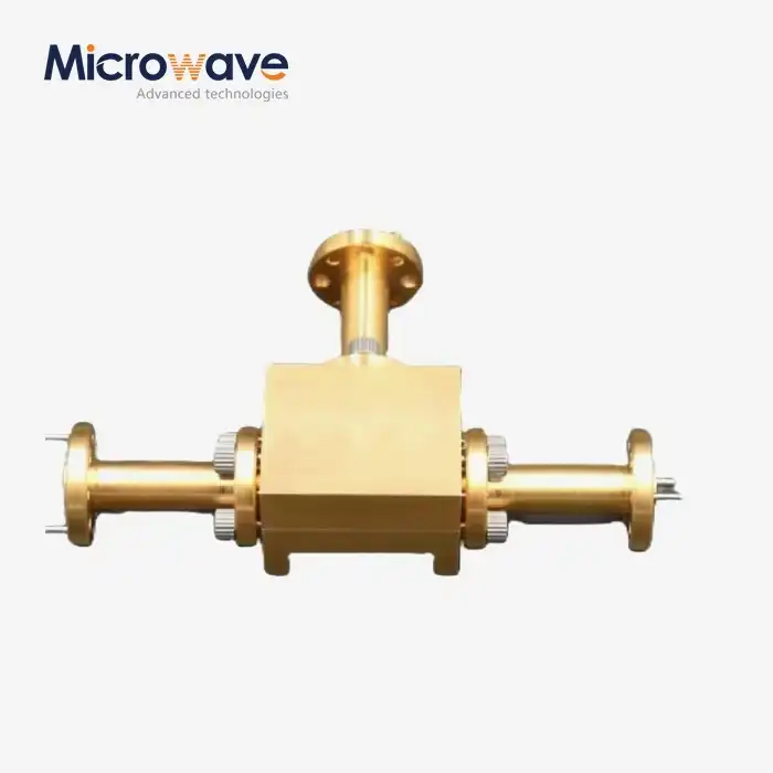
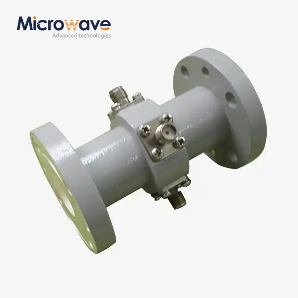
A waveguide low-pass filter is a passive RF part that lets signals below a certain frequency pass through but stops signals above that frequency. In contrast to coaxial or microstrip designs, it controls wave propagation by the shape of a waveguide cavity, such as corrugated ridges, stepped impedance sections, or waffle-iron structures. This method has lower insertion loss (usually less than 0.1 dB in the passband) and can handle more power than planar methods, so it is the best choice for high-power microwave systems.
What Is Stopband Attenuation and Why Does 100 dB Matter?
In decibels, stopband attenuation shows how much a filter blocks out frequencies that aren't wanted outside of the passband. Most standard waveguide filters can block signals by 60 to 80 dB. When you reach 100 dB, the unwanted signal power is cut by a factor of 10²⁰. This is a very high amount of separation. This is important in systems where even small amounts of harmonic energy can mess up channels next to them, make measurements less accurate, or break the rules in permitted frequency bands.
Key Parameters That Define Filter Performance
There are three main factors that determine if a filter can get close to 100 dB attenuation: the number of filter sections (poles), the quality of the conductor surfaces, and how accurate the cavity measurements are. About 20 dB of slope is added to the stopband by each extra filter section. A good filter is different from a high-specification filter that can be used in defense or satellites because it matches all three factors through strict production control.
Technical Challenges to Achieving 100 dB Stopband Attenuation
The Insertion Loss vs. Attenuation Trade-Off
Adding more filter sections makes stopband rejection better, but it also makes passband insertion loss worse. Engineers have to carefully balance these different needs. This trade-off needs to be done over and over again using EM models and component-level tuning for applications that need both low loss (< 0.2 dB) and deep rejection (≥ 100 dB). To do this, you need experienced RF design teams and measurement tools that can check attenuation beyond 80 dB.
Material and Surface Quality Constraints
At microwave frequencies, skin-depth losses are directly affected by how rough the surface of the conductor is. At frequencies above Ka-band, even small flaws in the surface spread energy and lower the effective absorption depth. For the least amount of loss, silver plating is best. Gold plating, on the other hand, is used in corrosive or wet places, even though it has a slightly higher resistance. Dielectric contamination inside the waveguide low pass filter cavity can further lower stopband performance. For filters that need to meet 100 dB specifications, hermetic sealing and clean manufacturing environments are essential.
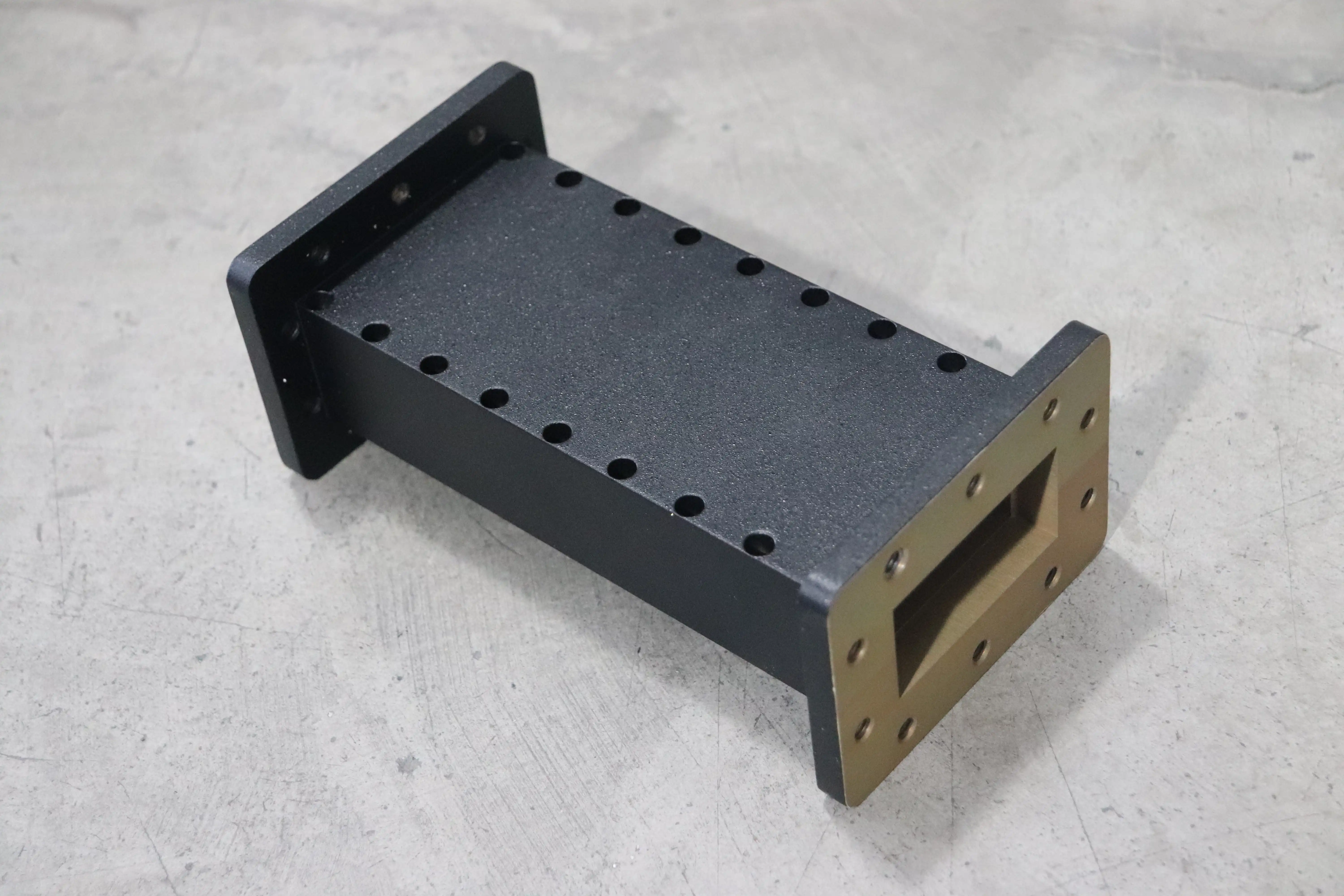
Limits of EM Simulation in Practice
EM modeling tools today, like CST Microwave Studio or ANSYS HFSS, can very accurately predict how filters will respond up to 80–90 dB of loss. After that point, numerical noise from simulations and production errors start to take over. To make sure that a manufactured filter really does achieve its stated 100 dB rejection, it needs to be checked in the lab using calibrated VNA systems and sometimes substitution measurement methods.
Comparing Waveguide Low Pass Filters with Alternative Technologies
A lot of the time, procurement engineers have to choose directly between waveguide, coaxial, and planar filter types. Each has a clear range of frequencies and power levels within which it can operate. The difference in performance becomes noticeable at higher frequencies and power levels.
Here's how the main types of filters stack up against each other:
- Waveguide low-pass filters offer the highest power handling (kilowatts CW, megawatts peak) and the deepest achievable stopband rejection. Waffle-iron designs suppress higher-order propagation modes, giving broader effective stopbands. They are larger and more expensive to machine, but nothing else matches their performance in high-power radar or satellite uplink applications.
- Coaxial filters from suppliers like Pasternack or Mini-Circuits are compact and cover wide frequency ranges, but they typically top out at 60–80 dB rejection and handle far less power. They suit laboratory and low-power system applications where size matters more than raw attenuation.
- Cavity and dielectric resonator filters offer very sharp roll-off responses and compact form factors, but consistently achieving 100 dB stopband rejection across a broad frequency range remains difficult. They excel in highly selective narrowband applications rather than broadband harmonic suppression.
These differences help B2B procurement teams match the right technology to the right system needs instead of picking the smallest or cheapest option when the job really needs waveguide-grade performance.
Practical Design Strategies and Manufacturing Considerations
Dimensional Control and Cutoff Frequency Tuning
To get 100 dB of reduction, you must first carefully control the size of the waveguide low pass filter channel. Even a small error of 0.01 mm in size at X-band or Ka-band frequencies can move the cutoff frequency and make the stopband slope worse. Standard practice is to use CNC to cut aerospace-grade aluminum (6061-T6) or copper and then check the dimensions afterward. Tight-tolerance inspections are done at every stage of production at ADM to make sure that the consistency of the filters is kept across OEM production runs.
Surface Treatment and Plating Selection
For low insertion loss in waveguide filters, silver plating is still the norm. When used outside on SATCOM stations or in military settings, gold plating over a nickel barrier layer protects against corrosion without affecting RF performance too much. Electroless plating methods cover complex cavity shapes more evenly than electroplating. This is important for waffle-iron structures with small holes inside them, since changes in plating thickness would cause resonant frequencies to shift.
Testing and Verification Protocols
Every high-specification filter needs to have its S-parameters checked with a calibrated VNA (VSWR < 1.2:1 is a standard acceptance threshold). This is followed by high-power testing to make sure the CW and peak power ratings are correct. For pressurized waveguide systems, finding helium leaks and keeping an eye on the pressure drop 24 hours a day are ways to make sure the seal is tight. The lab at ADM has measuring tools that can work up to 110 GHz, which lets them fully check the performance of filters across microwave and millimeter-wave frequency ranges before sending them out.
Real-World Applications Needing Ultra-High Stopband Attenuation
There is one thing that all defense radar transmitters, satellite uplink earth stations, and medical linear accelerators need: the RF spectrum that leaves the transmitter must be clean. In military radar systems, unwanted harmonic emissions can show where the emitter is or cause problems with sensors that are close by. In Ku-band and Ka-band SATCOM uplinks, harmonics that fall in neighboring satellite bands are not allowed by the ITU and could lead to claims of interference. When harmonic energy is put into the structure that speeds things up in medical LINACs, it lowers the quality of the beam and makes treatment less accurate.
New 5G millimeter-wave infrastructure also makes more people want to use it. As base stations work at 28 GHz and 39 GHz, harmonic products fall in licensed bands that are close by. This makes high-rejection waveguide filtering more important for network compliance. ADM provides waveguide components to these industries. Their goods are certified to ISO 9001:2015 and RoHS standards, which helps defense and aircraft procurement teams keep track of their supply lines.
Conclusion
It is scientifically possible for a waveguide low pass filter to have 100 dB stopband loss, but it needs careful engineering in the design, materials, and production. Precision CNC cutting, silver or gold finishing, waffle-iron and corrugated layouts, and thorough laboratory testing are all important parts of the process. If procurement workers are looking for filters for radar, satellite, defense, or 5G infrastructure uses, knowing these factors will help them avoid buying parts that aren't exactly what they're supposed to be and that cause problems further down the line. With 20 years of experience making waveguide components, ADM is well-equipped to meet these needs from the concept stage through production.
FAQ
Can any waveguide low pass filter reach 100 dB attenuation?
Not all styles can do it. For 100 dB, you need a lot of filter sections (usually seven or more poles), areas that are plated with a high-conductivity material, and very close specs on the sizes of the parts. Most standard catalog filters list 60–80 dB. To consistently hit 100 dB, you need custom-engineered systems and production methods that have been tested.
How does a waffle-iron filter differ from a corrugated design?
Longitudinal ridges in corrugated filters make stepped impedance sections, which mostly change the main transmission mode. When broadband harmonic rejection is needed, waffle-iron designs have transverse holes that also block higher-order waveguide modes. This makes the effective stopband larger, which is a big plus.
What is the typical insertion loss for a high-attenuation waveguide filter?
Even when the stopband rejection is very high, well-designed waveguide low-pass filters keep the insertion loss below 0.2 dB in the passband. The exact number relies on the frequency, the order of the filters, the quality of the conductors, and the type of plating used.
How are these filters tested before shipment?
In addition to VNA-based S-parameter testing, ADM also does high-power validation, flange flatness inspection, and helium leak testing for pressurized configurations. Up to 110 GHz is what our lab can handle.
Request a Custom Waveguide Low Pass Filter Quote from ADM
ADM has been a trusted waveguide low pass filter maker for over 20 years, sending high-precision RF parts to companies around the world in defense, satellite, and telecom. Our engineering team lets you make any changes you want, from the cutoff frequency to the power rating. They are backed by ISO 9001:2015 certification and 110 GHz lab verification. To get a datasheet or production quote right away, email your requirements to craig@admicrowave.com.
References
1. Matthaei, G. L., Young, L., & Jones, E. M. T. — Microwave Filters, Impedance-Matching Networks, and Coupling Structures, Artech House, 1980.
2. Pozar, D. M. — Microwave Engineering, 4th Edition, John Wiley & Sons, 2011.
3. Cameron, R. J., Kudsia, C. M., & Mansour, R. R. — Microwave Filters for Communication Systems, John Wiley & Sons, 2007.
4. IEEE Transactions on Microwave Theory and Techniques — "Design of Waffle-Iron Filters with Extended Stopband Performance," Vol. 58, No. 7, 2010.
5. IEC 62037-1 — Passive Intermodulation (PIM) Measurement Standard for RF Components, International Electrotechnical Commission, 2012.
6. Levy, R., & Cohn, S. B. — "A History of Microwave Filter Research, Design, and Development," IEEE Transactions on Microwave Theory and Techniques, Vol. 32, No. 9, 1984.