





Single Channel Coaxial Rotary Joint Specs That Decide Radar Performance
When a radar antenna spins at several hundred RPM while transmitting high-power pulses, the RF signal path cannot afford a single moment of interruption. A single channel coaxial rotary joint sits at that exact interface—between the stationary transmitter and the rotating antenna—quietly deciding whether the radar sees its target clearly or misses it entirely. Choosing the wrong specs here does not just degrade performance; it can ground an aircraft, blind a naval vessel, or compromise a surveillance network. This guide breaks down what actually matters.
Understanding Single Channel Coaxial Rotary Joints: Core Concepts and Design Principles
What This Component Actually Does
A coaxial rotary joint is an inactive electromechanical device that sends RF and microwave signals across a rotating contact while keeping the characteristic impedance under control, which is usually 50Ω. It works on Transverse Electromagnetic (TEM) mode principles, which let it spin in a circle without stopping or wearing out the wire. This fixes the "cable wrap" problem right away, which happens when one part of a system keeps rotating around another part.
Materials and Construction
The body is usually made from passivated aluminum or stainless steel (303/304 grade), which blocks electromagnetic waves and doesn't rust. Beryllium Copper (BeCu) with gold-on-gold treatment is used for the internal contacts. This keeps the contact resistance low even after millions of spinning cycles. These choices of materials were made on purpose because they have a direct effect on how long field-deployed radar systems last and how clean the signals they send.
Impedance Matching and Rotational Stability
To keep 50Ω impedance throughout spinning, you need to be very careful with the contact shape and the limits of the machining. Any change causes reflections that make the VSWR bigger and mess up the radar return signal. Good designs keep Phase WOW (the change in phase during spin) within ±1° to ±5°, which is very important for the accuracy of pulse Doppler and phased-array radar processing.
Key Specifications That Influence Radar Performance
Frequency Range, Insertion Loss, and VSWR
The electrical part of any RF rotary joint test is built around these three specs. The frequency limit is set by the connector interface. SMA works from DC to 18 GHz, 2.92 mm up to 40 GHz, and 2.4 mm up to 50 GHz. For well-built units, VSWR stays below 1.30:1, and insertion loss stays below 0.3 dB. When operating at longer ranges, even a 0.5 dB rise in insertion loss can make radar detection range much shorter.
Power Handling and Phase Stability
These are the details that buying teams often miss until they lead to a failure in the field:
- Average power handling: Continuous-duty radar transmitters require single channel coaxial rotary joints rated for average power levels, not just peak ratings. Insufficient average power handling causes thermal drift and contact degradation.
- Phase WOW: Variation in phase angle during rotation directly impacts moving target indication (MTI) processing. Tighter WOW figures—below ±2°—are preferred for modern digital signal processing.
- Return loss: Values above 20 dB (VSWR < 1.22:1) reduce signal reflections that could saturate the receiver front end.
You can be sure that these parameters are correct by checking the supplier's test datasheet with a Vector Network Analyzer (VNA) and seeing that the S-parameter readings cover the whole frequency range.
Mechanical Endurance and Rotation Speed
Weather radar devices work 24 hours a day, seven days a week, and their sensors are always turning. A good coaxial rotary joint can work at speeds of 10 RPM to over 5,000 RPM and can last for tens of millions of rotations. The temperature range for operation should be at least -55°C to +85°C, and MIL-STD-810 compliance proves that it can be used in both air and sea conditions.
Single Channel Coaxial Rotary Joint vs. Alternative Solutions
Comparison With Slip Rings and Multi-Channel Joints
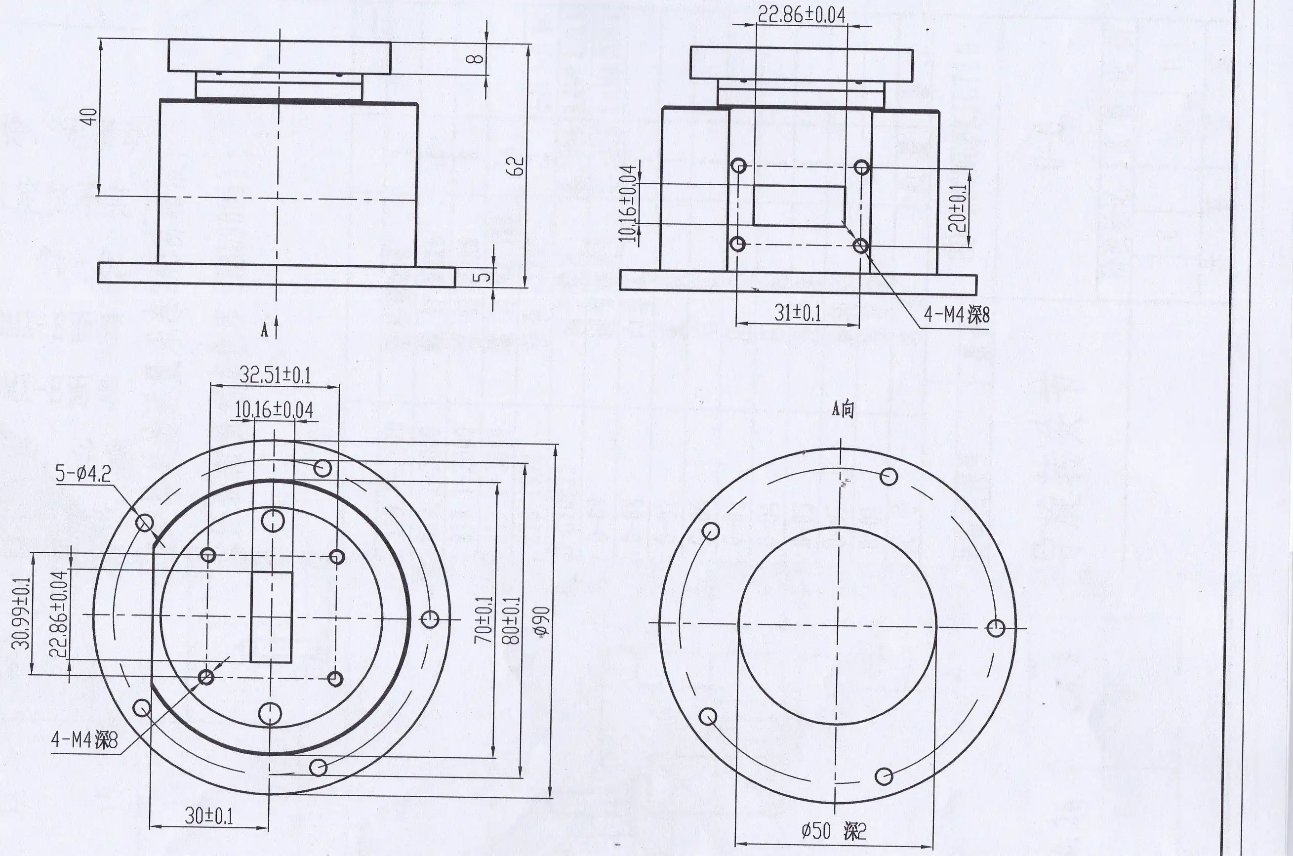
Electrical slip rings that are used in most devices work well with low-frequency signals and DC power, but they lose their ability to control impedance above a few hundred MHz. At microwave frequencies, where slip rings just don't work, a single-channel coaxial system keeps the signal's purity. Multi-channel rotary joints add more channels so that multiple data lines can be used at the same time, but they are bigger, heavier, and cost more, which are all things that matter for platforms that need to be small or airborne.
Comparison With Fiber Optic Rotary Joints
Fiber optic rotary joints (FORJs) work well with digital data streams and don't let EMI get through. But at each end, they need to be changed from optical to electrical, which adds latency and component count. In radar systems, where the information is already at microwave frequency, a coaxial rotary joint is still the best and most cost-effective way to send RF directly.
Industry Reference Points
Moog and Cobham are two companies that have been making coaxial rotary joints for defense radar projects for a long time. Their catalog specs are helpful as standards: for defense-grade units, average insertion loss is less than 0.2 dB, VSWR is less than 1.25:1, and lifetimes are more than 100 million spins. ADM's products are made to meet these same levels of performance while also being more flexible for OEMs and allowing for faster prototyping.
Practical Applications and Case Studies in Radar Systems
Airborne and Ground-Based Radar Platforms
The single channel coaxial rotary joint in air traffic control radar sends high-power waves from an emitter that stays still to an antenna that keeps turning. Target resolution is directly affected by phase stability during rotation. In aircraft early warning systems, designers have to deal with limited space and weight, so they have to use small SMA-interface joints that can handle large changes in temperature and pressure according to MIL-STD-810.
Maritime and SATCOM Applications
Navigation radar on ships and SATCOM-on-the-go systems both need to be able to track movement all the time. To work in marine settings, you must have IP65 or IP67 ingress protection grades and be able to withstand salt spray (tested according to ASTM B117). Vehicle-mounted satellite terminals use coaxial rotary joints in the antenna pedestal to keep Ka/Ku/X-band links going even when the platform moves. This requires both high-frequency performance and mechanical durability.
Troubleshooting Common Field Issues
Signal dropouts that happen sometimes in spinning radar systems are often caused by worn contact surfaces or not enough starting force. Drive motor overload can be avoided by choosing a joint with written power numbers for both starting and running. Before buying, the supplier's quality paperwork should include life cycle testing data that proves the rotational endurance under the system's real job cycle.
How to Choose the Right Single Channel Coaxial Rotary Joint for Your Radar System
Define Electrical and Mechanical Requirements First
Start with the frequency at which the radar works and work your way back to the connector interface. Then, check the budget for VSWR, power handling, and phase stability. Check the technical needs, such as the speed of spinning, the range of temperatures, the level of vibration, and the level of defense against water getting in. It saves a lot of time to write these down as official specifications before getting in touch with providers.
Evaluate Supplier Quality Credentials
Having ISO 9001:2015 certification is a basic sign that a supplier uses controlled production methods. RoHS certification is important for exporting to the U.S. market. Instead of just depending on the numbers on the datasheet, ask for real VNA test results, like S11 and S21 plots across the whole frequency range. Suppliers who give test results for each unit show that they really care about quality control.
Balance Cost, Lead Time, and Customization
Lead times are shorter, and unit costs are lower for standard catalog configurations. Custom designs, like certain connector pairs, non-standard housing measurements, or higher temperature values, need more time to test the prototype. ADM provides fast prototyping services with full technical support. This shortens the proof cycle for OEM programmers who are working to meet program deadlines.
Conclusion
Specifications for a single channel coaxial rotary joint are not just numbers. They include things like insertion loss, VSWR, phase WOW, power handling, and mechanical durability. Each one has a direct effect on how well a radar system finds targets, keeps signals coherent, and works in real-world situations. When procurement experts know about these factors, they can make better decisions about where to source goods and lower the risk of mistakes in the field. ADM is a good partner for radar system designers looking for reliable RF rotary joint solutions because it has a lot of experience making precise microwave components and has approved quality systems and technical support.
FAQ
What frequency range does a single channel coaxial rotary joint typically cover?
Coverage depends on how the connection is connected. Designs based on SMA can work from DC to 18 GHz, 2.92 mm (K connector) can go up to 40 GHz, and 2.4 mm can go up to 50 GHz. There are 1.85 mm and 1.0 mm connectors for millimeter-wave uses above 50 GHz. Measured S-parameter data, not just nominal specifications, should always be used to confirm the frequency range.
How do I reduce insertion loss in my radar signal path?
Choose a coaxial rotary joint that has been precision-machined on the inside and has gold-on-gold contact plating. Reduce the length of the cable and the number of connector changes at each end. Make sure that the insertion loss is recorded at the real working frequency, since loss usually goes up as frequency goes up. For long-lasting uses, make sure that the insertion loss standard stays the same over the rated rotary lifetime.
When is a single-channel design preferred over a multi-channel joint?
When space or weight limitations are important, and only one RF signal path needs to be sent, a single-channel coaxial rotary joint is the best choice. Multi-channel joints let more data come in at the same time, but they make the housing bigger, heavier, and more expensive. Most regular pulse radar systems only have one transmit/receive channel, so the single-channel configuration is best for both electrical performance and mechanical ease of use.
Partner With ADM for Your Coaxial Rotary Joint Needs
For more than 20 years, ADM has been making precise RF and microwave parts. Their production is ISO 9001:2015 and RoHS-certified. ADM is a reliable company that provides single channel coaxial rotary joints. They can be customized for OEMs, prototypes can be made quickly, and full VNA test documents are provided. Our engineering team is ready to help you with your purchase, whether you need a basic setup or a solution that is made just for your defense radar or SATCOM program. To get a price, email us at craig@admicrowave.com.
References
1. Pozar, David M. Microwave Engineering, 4th ed. — Wiley, 2011.
2. IEEE Standard 149-1979, IEEE Standard Test Procedures for Antennas — IEEE, 1979.
3. Skolnik, Merrill I. Introduction to Radar Systems, 3rd ed. — McGraw-Hill, 2001.
4. MIL-STD-810H, Environmental Engineering Considerations and Laboratory Tests — U.S. Department of Defense, 2019.
5. Microwave Journal, "Rotary Joint Design Considerations for Radar and Satcom Applications" — Microwave Journal, 2018.
6. ASTM B117-19, Standard Practice for Operating Salt Spray (Fog) Apparatus — ASTM International, 2019.
YOU MAY LIKE
 VIEW MOREWG Circulator
 VIEW MOREWaveguide Calibration Kits
 VIEW MOREWaveguide Sliding Short
 VIEW MOREWaveguide Adjustable Support
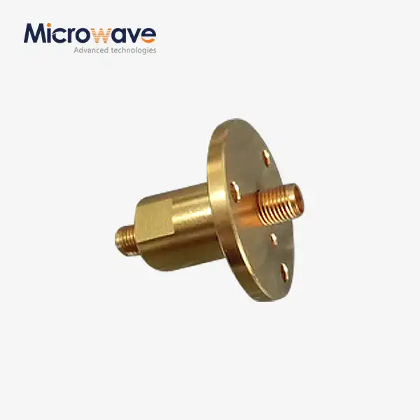 VIEW MORESingle Channel Coaxial Rotary Joint
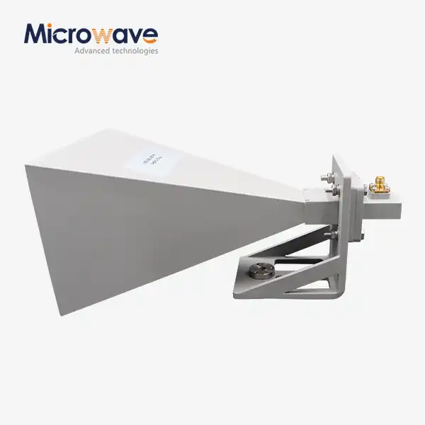 VIEW MOREStandard Horn Antenna
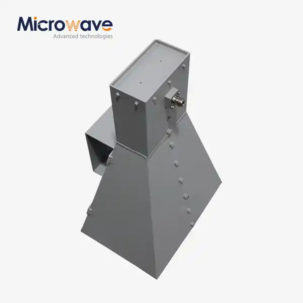 VIEW MOREWideband Double-ridged Horn Antenna
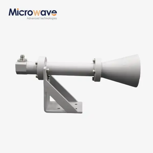 VIEW MOREDual Linear Broadband Circular Polarization Horn Antenna
