


Why Multi-Mode Matching Matters in Waveguide Low Pass Filter Design?
A big problem we face when making high-frequency transmission systems is making sure that electromagnetic data moves through waveguide structures without getting reflected or lost. This problem is solved by multi-mode matching in waveguide low pass filter design. These specialised RF parts have to take into account the fact that the waveguide structure has more than one electromagnetic mode at the same time. The main ones are transverse electric (TE) and transverse magnetic (TM) modes. If multi-mode matching isn't done right, filters have higher insertion loss, worse bandwidth performance, and weaker signal integrity. The waveguide low pass filter only works at its best when engineers carefully consider how these modes couple, interact, and spread through physical changes and breaks when they are designing it.
Understanding the Importance of Multi-Mode Matching in Waveguide Low Pass Filters
For a waveguide low pass filter to work, it needs to let frequencies below a certain limit pass through while severely attenuating higher frequencies. When we realise that electromagnetic energy moves through waveguide devices in different ways, this job that seems simple becomes harder.
Why Waveguide Modes Matter
Waveguide structures can easily support a number of different electromagnetic field configurations, each with its own cutoff frequencies and field ranges. The TE10 mode, which has the lowest cutoff frequency, is the main mode in most rectangle waveguides. When the working frequency goes above their respective cutoff levels, higher-order modes like TE20, TE01, and different TM configurations can spread. These modes don't just live together without interacting; at every geometric change, they do interact, causing reflection, conversion, and coupling effects that have a direct effect on how well the filter works.
The Link Between Mode Behavior and Filter Performance
When engineers make waveguide low pass filters, they have to correctly guess how energy moves between different modes as signals pass through internal features such as stepped resistance sections, cavity resonators, and corrugated ridges. Each geometry break could cause unwanted higher-order modes to appear, even if the signal coming in is only the fundamental mode. When we don't take these multi-mode interactions into account during the design process, the filter has a frequency response that is hard to predict, insertion loss characteristics that aren't as good, and voltage standing wave ratio (VSWR) performance that is very different from what was specified. Our work at Advanced Microwave Technologies Co., Ltd shows that a deep understanding of waveguide theory and multimode propagation is necessary to get the best electromagnetic performance in aerospace, defence, and satellite communications, all of which are mission-critical.
Common Challenges in Waveguide Low Pass Filter Design Due to Multi-Mode Effects
A lot of purchase engineers and system designers have been frustrated when they get waveguide low pass filters that don't work with the system they were supposed to work with. Most of the time, these performance problems are caused by designers and manufacturers not taking multi-mode effects into account enough during the design and production stages.
Performance Degradation Symptoms
When multi-mode management isn't done right, the most obvious effect is more insertion loss than expected. Unexpectedly, signals that should pass through the filter are weakened, which makes the system less efficient and requires more emitter power to make up for it. Bandwidth inconsistencies are another common sign. This happens when the real passband width is very different from what was planned, which could mean that important working frequencies are missed or unwanted signals get through. The quality factor (Q-factor) also goes down, which makes the cutoff features less sharp and the ability to choose between the passband and stopband regions less strong.
Root Causes of Multi-Mode Problems
Unwanted mode excitation and spread are caused by a number of production and design factors. When there are breaks in the shape of a waveguide, especially where two filter sections with different cross-sectional sizes meet, they cause impedance mismatches that move energy from the basic mode to higher-order modes. Tolerances in manufacturing are also very important; even small changes from the exact dimensions can move cutoff frequencies and change how mode fields are distributed. Material flaws, like rough surfaces inside the waveguide and uneven coating thickness, cause extra losses and echoes that take on more significance as the frequency goes up.
When using a lot of power, these problems get even worse because you have to think about multipactor effects and voltage breakdown. To get to the bottom of these problems during the design phase, we need advanced electromagnetic simulation tools along with strict manufacturing process controls. These are skills that we've been working on for more than 20 years at Advanced Microwave Technologies Co., Ltd., where our measurement systems go up to 110 GHz and our 24m Microwave Darkroom lets us test filter performance precisely in real-world settings.
Design Principles and Techniques for Effective Multi-Mode Matching
Successfully mitigating multi-mode effects requires a methodical approach that combines theoretical knowledge with real-world planning and validation methods.
Geometry Optimization Strategies
One of the best ways to control mode transmission is to use structures with stepped resistance. Engineers make impedance changes that keep the energy of the basic mode while blocking higher-order modes by carefully planning the sizes and spacing of each filter section that comes after it. Tapered shifts between sections make geometric changes less sudden, which lowers the chance of reflections and mode conversion at important surfaces. The corrugated ridge and waffle-iron internal structures take advantage of the different ways that different modes can spread. They do this by blocking out unwanted modes while keeping the basic mode's low-loss transmission.
Mode Suppression Techniques
Dedicated mode suppressors built into the filter structure specifically weaken higher-order modes while not having a big effect on the main mode that is wanted. These can be resistive cards, lossy dielectric materials, or geometric shapes that are designed to interact with troublesome modes. Careful thought needs to go into where and how these suppressors are placed so that they don't create new mode conversion points and stop unwanted spread.
Simulation and Validation Approaches
Modern electromagnetic modelling software has changed the way we can predict how multimode devices will behave before making a real prototype. Full-wave three-dimensional study of filter structures can be done with tools like HFSS, CST Microwave Studio, and COMSOL Multiphysics. These tools show mode field distributions, coupling coefficients, and scattering factors over a wide frequency range. In addition to simulations, we do a lot of testing in our Antenna Plane Near and Far Field Measuring Recombination Chamber. This lets us make sure that the waveguide low pass filters work well in situations that are very similar to real-world working settings. By using both simulations and real-world tests, we've been able to consistently produce high-quality filters that meet the strict requirements of aerospace, satellite ground stations, and high-power radar systems, where even a small change in performance can affect how well the whole system works.

Benefits and Applications of Proper Multi-Mode Matching in Waveguide Low Pass Filters
Implementing multi-mode matching principles correctly by engineers leads to performance gains that are noticeable in a wide range of system factors and practical situations. When waveguide low pass filters are properly matched, their insertion loss values are very close to theoretical minimums, often below 0.1 dB in the passband. This keeps the signal strength and lowers the power needs of emitters.
Measurable Performance Improvements
VSWR values usually fall below 1.2:1, which means that maximum power is transferred and echoes that could damage upstream parts are kept to a minimum. The operating bandwidth gets bigger, which lets frequency changes happen and gives the system more options. The cutoff slope gets steeper, making the line between the passband and stopband regions clearer. This improves spectral clarity and regulatory compliance.
Mission-Critical Application Benefits
These improvements in speed have direct benefits at the system level. In satellite uplink terminals, waveguide low pass filters that are properly built keep harmonics from high-power amplifiers from interfering with transponders next to them. This protects both operating reliability and compliance with regulations. Better signal integrity and fewer unwanted emissions help defence radar systems find and classify targets more clearly, even in electromagnetic settings with a lot of interference. The thermal stability and mechanical strength of waveguide structures are important for aerospace guidance systems because they keep working well in high and low temperatures and with vibrations that would damage coaxial or microstrip options.
Advantages for B2B Procurement
Companies that want OEM solutions for custom RF systems find that filters made with the right multi-mode matching work better with other parts. The expected performance cuts down on the time needed to qualify the system at the system level and lowers the risk of problems in the field. If you build waveguide structures correctly, they will last a long time even in harsh settings. This is especially true if they are made with precision machining from high-conductivity materials and finished with the right plating. Because these filters are customisable, they can be made to fit the needs of a system perfectly, meeting frequency plans, power handling needs, and mechanical input limitations that standard parts can't.
Comparing Waveguide Low Pass Filters With Other Filter Types
To choose the right filter technology, you need to know the basic pros and cons of each execution method and how multi-mode matching changes these differences.
Waveguide Versus Planar Technologies
Microstrip and stripline filters come in small packages and are easy to connect to printed circuit boards, which makes them good for uses that need to be small. However, these flat technologies have a lot more insertion loss, especially at microwave and millimeter-wave frequencies, where skin effect and dielectric losses are more noticeable. On the other hand, waveguide designs have very little loss because electromagnetic energy mostly moves through air or space, not through dielectric substrates that lose energy. Power handling varies a lot, too. Planar filters can handle a few watts to tens of watts of power, but waveguide low pass filters that are properly built can handle kilowatts of constant power and megawatts of peak power without arcing or thermal damage.
Comparison With Other Waveguide Filter Types
Different from other filters, waveguide bandpass filters pick out a certain frequency range while blocking both low and high frequencies. Most of the time, these use coupled-resonator or resonant cavity arrangements. High-permittivity materials are added to dielectric-loaded waveguide filters to make them smaller. These materials shorten the wavelength at a particular frequency. When we look at these versions next to low-pass filters that are designed to match multiple modes, the low-pass setup has better mode purity because it doesn't need the complicated resonant structures that can accidentally trigger higher-order modes. When low-pass filters are well built, they often have a higher quality factor than band-pass filters. This is because the simpler internal geometry reduces the number of loss processes. Knowing these differences helps procurement professionals and design engineers choose the best filter topology for their needs.
Procurement Considerations for Waveguide Low Pass Filters Addressing Multi-Mode Matching
Finding high-performance waveguide low pass filters involves looking at more than just the electrical specs. This is especially true when multi-mode matching has a big impact on how well the system works.
Evaluating Manufacturer Expertise
Because multi-mode design is so complicated, you need to work with suppliers who really understand electromagnetics instead of just making things from plans. Look for proof that they have advanced measurement tools, the ability to simulate things in-house, and a history of solving problems similar to yours. Manufacturers should be able to talk about methods for blocking modes, explain how they use geometric optimisation, and give S-parameter data that clearly shows proper mode control across the given frequency range.
Technical Documentation and Support
A full datasheet should have more than just basic specs like insertion loss and cutoff frequency. It should also have detailed info about VSWR, harmonic rejection levels, power handling under certain operating conditions, and physical specs like flange compatibility and pressurisation options. You can tell the difference between suppliers who understand your problems and those who just sell generic parts by the application notes, design guides, and quick expert help they offer.
Customization and Delivery Considerations
Most of the time, standard catalogue filters don't meet the exact needs of mission-critical systems. Check to see if possible providers can customise their products for OEMs. This includes seeing if they are willing to change designs to fit specific frequency plans, mechanical interfaces, and environmental needs. Timelines for prototyping are important, especially during the development phase when changes may need to be made over and over again. The cost of ownership and integration risk are affected by things like production wait times, quality certifications like ISO 9001, and paperwork for RoHS compliance. We at Advanced Microwave Technologies Co., Ltd can make filters that meet the exact needs of defence contractors, satellite system integrators, and research institutions all over the world.
Conclusion
When designing a waveguide low pass filter, multi-mode matching is an important thing to think about because it has a direct effect on insertion loss, bandwidth, selectivity, and the general performance of the system. Because electromagnetic modes interact with waveguide structures in a lot of different ways, they need complicated design methods that combine geometry optimisation, mode suppression techniques, and thorough proof through simulations and real-world tests. People who work in procurement who need reliable, high-performance filters for use in aircraft, defence, radar, and satellites should look for providers who have experience with multi-mode design, full testing facilities, and a history of doing well in mission-critical settings. As microwave and millimeter-wave systems keep getting better at higher frequencies and meeting stricter performance standards, it will become even more important to match multiple modes correctly.
FAQ
1. What specific advantages does multi-mode matching provide in waveguide low pass filters?
In waveguide low pass filters, multi-mode matching cuts down on unwanted mode activation at geometric breaks, which lowers insertion loss and raises VSWR. This makes the cutoff characteristics sharper, the useful bandwidth larger, and the performance more stable as temperature and power change. Systems gain from better signal quality and fewer unwanted emissions.
2. How does multi-mode matching affect insertion loss?
When multi-mode matching is done right, it stops energy from coupling into higher-order modes that either don't spread well or cause resonances in the filter structure. This keeps the signal energy focused on the fundamental mode, which leads to insertion loss values that are close to theoretical minimums—often less than 0.1 dB in the passband for good waveguide designs.
3. Which simulation tools accurately model multi-mode effects?
Standard tools in the field that can do full-wave three-dimensional electromagnetic analysis are HFSS, CST Microwave Studio, and COMSOL Multiphysics. These methods figure out the field distributions for all propagating and evanescent modes. This lets designers guess how modes will change, couple, and spread in complicated filter shapes before making a real prototype.
Partner With ADM for Superior Waveguide Low Pass Filter Solutions
We at Advanced Microwave Technologies Co., Ltd are ready to meet your most difficult waveguide low pass filter needs with custom-engineered solutions backed by more than 20 years of microwave experience. Our team of experienced engineers specialises in multi-mode matching design. To make sure the performance is good before shipping, they use cutting-edge modelling tools and our state-of-the-art 24m Microwave Darkroom, which can measure up to 110 GHz. We offer ISO 9001-certified quality and full technical support throughout the whole procurement and integration process, whether you need ruggedised filters for defence radar systems, high-power solutions for satellite ground stations, or OEM designs that are made just for you. For mission-critical applications, contact our engineering team at craig@admicrowave.com to talk about your needs and find out why top military companies, telecommunications system designers, and research institutions trust ADM as their supplier.
References
1. Marcuvitz, N. (1986). Waveguide Handbook. Institution of Engineering and Technology, London, UK.
2. Collin, R. E. (2001). Foundations for Microwave Engineering (2nd Edition). Wiley-IEEE Press, New York, NY.
3. Ragan, G. L. (1948). Microwave Transmission Circuits. McGraw-Hill Book Company, New York, NY.
4. Levy, R. (1976). "Filters with Single Transmission Zeros at Real or Imaginary Frequencies." IEEE Transactions on Microwave Theory and Techniques, vol. 24, no. 4, pp. 172-181.
5. Jarry, P., & Beneat, J. (2008). Advanced Design Techniques and Realizations of Microwave and RF Filters. Wiley-IEEE Press, Hoboken, NJ.
6. Matthaei, G. L., Young, L., & Jones, E. M. T. (1980). Microwave Filters, Impedance-Matching Networks, and Coupling Structures. Artech House, Norwood, MA.
YOU MAY LIKE
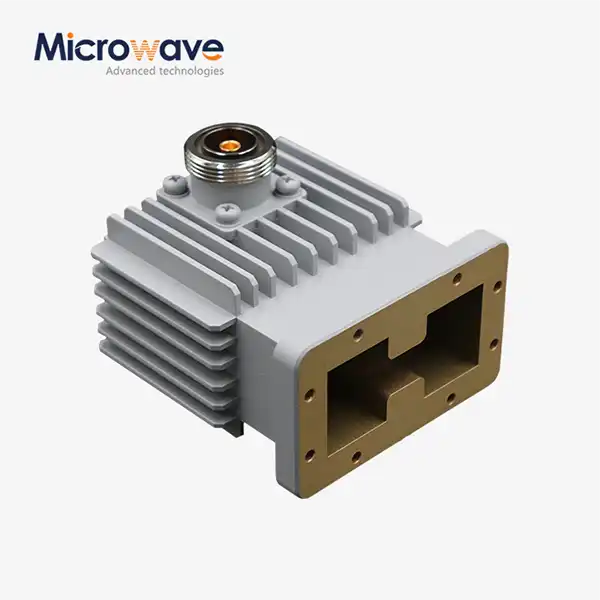 VIEW MOREHigh Power Waveguide to Coaxial Adapter
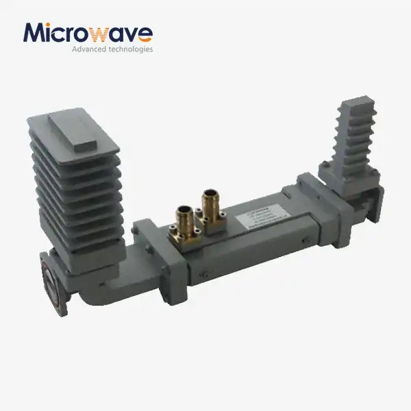 VIEW MOREHigh Power Waveguide Differential Phase Shift Isolator
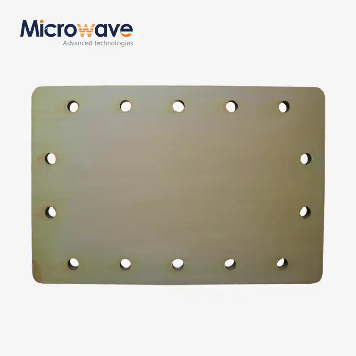 VIEW MOREWaveguide Short Plate
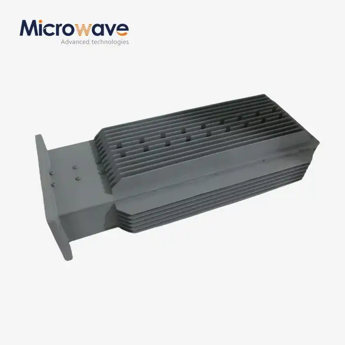 VIEW MOREDouble Ridge Waveguide Load
 VIEW MOREWaveguide Flange Gasket
 VIEW MOREDigitally Controlled Phase Shifter
 VIEW MOREMini Wideband Double-ridged Horn Antenna
 VIEW MOREDual Linear Broadband Dual Circular Polarization Horn Antenna
