Why Cassegrain Antennas Beat Parabolic Dishes at mmWave?
Because they have two reflectors, cassegrain antennas always work better than standard parabolic dishes for millimeter wave (mmWave) uses. The feed system is placed behind the main reflector in this design, which greatly lowers waveguide loss. This is very important for frequencies above 30 GHz, where even small transmission line losses can ruin link budgets. The bent optical path that comes with Cassegrain setups makes the aperture more efficient, the beam more tightly controlled, and the Gain-to-Noise Temperature (G/T) ratios better. These speed improvements directly lead to more stable satellite links, clearer radar returns, and faster communication systems in places where time is of the essence.
Understanding Cassegrain Antennas and Parabolic Dishes
Modern satellite communications, 5G infrastructure, and high-frequency networking are moving forward at speeds that have never been seen before, thanks to mmWave technology. The people in procurement who are in charge of choosing antennas have to make choices that have a direct effect on the dependability of the system, the costs of running it, and its place in the market. If you choose between dual-reflector systems and regular single-reflector dishes, your network will either meet design requirements or fall short during important activities.
We've seen this problem personally at Advanced Microwave Technologies Co., Ltd., where we've worked for 20 years with defense companies, telecom integrators, and research institutions to find a clear pattern. Companies that need to send precise signals at Ka-band and V-band frequencies are choosing Cassegrain designs over normal parabolic ones more and more. This choice comes from basic differences in architecture that become clear as working frequencies rise into the mmWave range.
The Cassegrain Architecture Explained
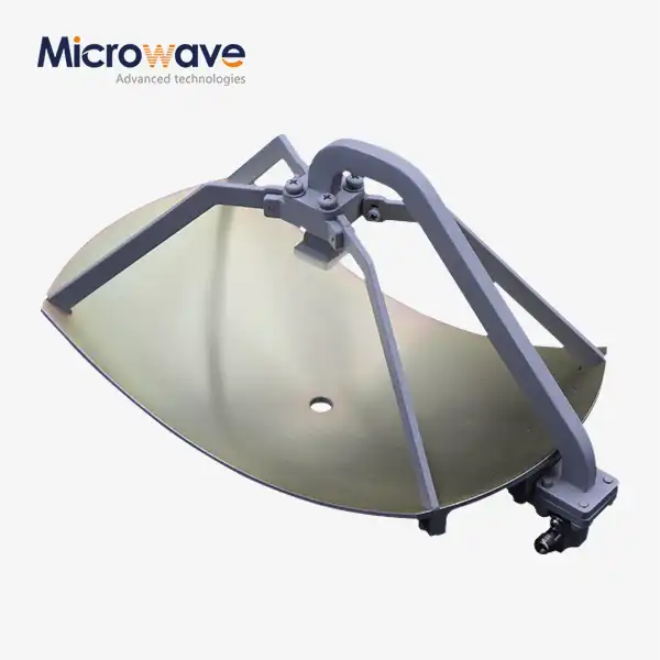
A Cassegrain antenna has two reflectors that work together: a big main parabolic dish and a smaller hyperboloidal sub-reflector that is placed close to the focal point. The feed horn is attached behind the primary reflector tip and sends signals to the sub-reflector. The sub-reflector then bounces the signals onto the main dish. This folded optical path makes the effective focal length longer without making the actual depth of the antenna deeper. This makes what engineers call a "compact range" shape.
A shallow f/D ratio of between 0.6 and 0.8 is common for the primary reflector. This makes it much smoother than prime-focus dishes. The sub-reflector can fit inside this shape, and the hyperbolic curve needed to focus electromagnetic waves stays the same. The sub-reflector has a hyperbolic shape that is exactly calculated to direct arriving parallel rays toward the phase center of the feed horn with the least amount of distortion.
How Standard Parabolic Dishes Differ
In traditional parabolic reflector antennas, signals come in through a single curved surface and are focused on a feed horn in front of the dish, which is at the focal point. This prime-focus design looks easier on paper, since it has fewer parts and clearer signal routes. Struts or a tripod structure that extends from the dish rim must hold up the feed horn and the electronics that go with it. This keeps heavy amps and receivers suspended in space.

This setup works well at lower microwave bands, from L-band to C-band. The bands stay long enough that the waveguide runs from the feed to the ground electronics, causing enough loss to be okay. Support systems that block feed have an effect on efficiency, but it stays within acceptable ranges. As the frequencies go up to Ka-band (26.5–40 GHz) and beyond, these trade-offs stop being technical trade-offs and start being performance problems.
Critical Performance Parameters at mmWave
In mmWave uses, there are three main factors that separate good antenna performance from great results. Gain tells you how well an antenna focuses the power it sends or picks up signals going in. The angle spread is determined by the beamwidth. Narrower beams are more directed. Side-lobe suppression stops signal leaks and interference from happening outside the main beam.
As the frequency goes up, the link between these factors gets harder to understand. If you use a 2.4-meter antenna at 12 GHz, you might get 46 dBi gain with good side-lobes. It is possible for the same physical aperture to hit 56 dBi at 30 GHz, but only if the surface accuracy, feed illumination, and blockage features are more precise. This is where the physical differences between the Cassegrain and prime-focus systems show up as performance gaps that can be measured.
Technical Advantages of Cassegrain Antennas at mmWave Frequencies
Engineers have known for a long time that dual-reflector antennas are better for demanding uses, but when it comes to procurement, decisions are often made based on familiar single-reflector choices. Knowing how the technical benefits of Cassegrain work helps buying teams make the case for investing in the best technology instead of settling for solutions that work.
Our testing facilities at Advanced Microwave Technologies Co., Ltd. have a 24-meter microwave lab that covers frequencies from 0.5 to 110 GHz. These facilities collect real-world data that backs up our statements about how well things will work. Both near-field and far-field tests show the same pattern: properly designed Cassegrain systems give 2-4 dB more gain and 5-10 dB better cross-polarization discrimination than prime-focus antennas with the same aperture at Ka-band and above.
Superior Gain and Radiation Pattern Control
Aperture efficiencies for Cassegrain antennas are between 60% and 70%, while those for prime-focus dishes of the same size are only 50 to 60%. This efficiency boost comes from the main reflector getting the right amount of feed light. The sub-reflector changes the voltage so that the feed horn can light up the main surface with a curved amplitude distribution that balances gain and spillover loss.
The bent optical path also makes the side-lobe function better. Before reaching the main dish, signals that bounce from the sub-reflector go through an extra step of focusing. This lowers the effects of diffraction at the edges of the reflector. This two-stage focusing makes the radiation patterns smoother, and the side-lobes are usually 3–5 dB lower than with prime-focus alternatives. Lower side-lobes directly lead to less interference in frequency bands that are already full, as well as better compliance with ITU-R S.580 regulatory filters.
Cross-polarization detection is more than 30 dB in well-designed Cassegrain systems, but only 20 to 25 dB in regular parabolic dishes. This is very important for satellite transmissions that use orthogonal polarisations to recover frequencies. Cross-pollution that doesn't work well lets signals leak between channels, which slows things down and needs more power reserves.
Minimized Feed System Losses at High Frequencies
As frequency goes up, signal loss through communication lines goes up by a huge amount. A 3-meter waveguide run from the feed to the receiver could cause 0.5 dB of loss at 12 GHz. At 30 GHz, the same length causes a loss of 1.5 dB. At 80 GHz, the loss is more than 4 dB. When system margins are already low, these numbers, which don't seem like much, destroy link budgets.
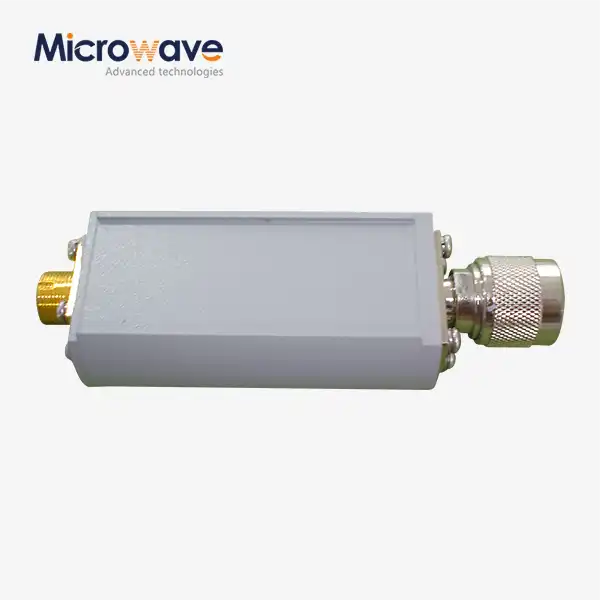
This issue is fixed by Cassegrain designs, which put the feed electronics right behind the main reflector and often within one meter of the feed horn. This geometry benefit gets rid of the need for long waveguide runs completely. Instead of being hung at focus points, high-power amplifiers are mounted on strong rear platforms. This makes installation easier and reduces the mechanical stress on precision parts.
Because it is mounted on the back, the feed electronics are also protected from direct sunlight and rain. When prime-focus dishes have feed horns that point up toward the sky, they catch rainwater and debris, so they need to be waterproof and have drainage holes. When the Cassegrain feed horns face downward toward the sub-reflector, they naturally shed water, protecting sensitive parts from the environment.
Compact Mechanical Structure and Wind Load Reduction
Because the optical path is bent, Cassegrain antennas can have long effective focal lengths while still having shallow physical shapes. A 3-meter Cassegrain dish might only be 0.6 meters deep, while a prime-focus version of the same size would be 1.2 meters deep. This small size makes wind loads less of a problem, which is very important for big antennas that need to stay pointed accurately during storms.
The project area and moment arm show how wind forces change with them. While the Cassegrain shape is shallower, it has less surface area that can be affected by wind. Also, the rear-mounted feed system focuses mass near the elevation rotation axis instead of extending it forward. Structural studies show that the wind loading is 30–40% lower for aperture sizes that are the same. This means that the base needs to be lighter, building costs will be lower, and the structure will be more stable in the long run.
High-end Cassegrain mirrors are made of carbon fiber composites or stretch-formed aluminum plates that keep the RMS surface accuracy at or above 0.2 mm. When the frequency goes to mmWave, where bands get smaller to millimeters, this accuracy is very important. At 30 GHz, a surface mistake of λ/20 (wavelength divided by 20) needs to be accurate to within 0.5 mm. At 80 GHz, the range drops to 0.19 mm. The thermal stability of carbon fiber keeps this consistency even at very high and very low temperatures, where other materials would bend.
Enhanced Noise Temperature Performance
As much as gain, antenna noise temperature decides how sensitive the system is. Lower noise floors make it possible to pick up weaker signals, which increases the range of contact and speeds up data transfer. The feed horn sees the cold sub-reflector instead of the warm ground, which is a subtle but strong way that Cassegrain antennas have better noise qualities.
Prime-focus feed horns look at the sky, but they can also see what's on the ground because the signal goes past the edge of the dish. Temperatures in the ground often hit 290 Kelvin, which makes the system noise a lot worse. The Cassegrain feed horn guides the sub-reflector down, and the sub-reflector only sees the sky. The sub-reflector's spillover mostly sees the cool sky (around 10 Kelvin) instead of the warm ground. This lowers the total antenna noise temperature by 10 to 20 Kelvin, which is a big deal for low-noise uses like radio astronomy and deep-space transmissions.
Practical Applications and Real-World Performance
Technical details are only useful when they lead to improvements in how things work. Before making a purchase choice, you need to know how the features of an antenna affect the success of a task in a variety of deployment situations. The examples below show how Cassegrain designs can add real business value, making their higher price point worth it compared to other options.
Satellite Earth Stations and Teleport Operations
Cassegrain antennas are the standard for teleport workers who deal with Ku-band, Ka-band, and V-band data. These buildings handle the uplink and downlink for High Throughput Satellites (HTS), which provide services for business internet, maritime communications, and aviation. There isn't much room for error in these systems' link budgets—rain fade at Ka-band can cause 6–8 dB of loss during storms.
Cassegrain designs give you the extra gain and efficiency you need to keep service going when the weather gets bad. A 7.3-meter Cassegrain antenna working at 30 GHz has a gain of about 64 dBi, while a prime-focus antenna has a gain of about 62 dBi. That 2 dB difference means that the Cassegrain system keeps signal levels that can be used even when bad weather would knock out other systems.
High-power amplifiers that are placed on the back have controlled thermal conditions and are easy to reach for servicing. Mean Time To Repair (MTTR) gains of 40 to 60 percent are reported by teleport operators compared to systems that need elevated work platforms to service electronics placed on feeds. When profits depend on service, faster fixes have a direct effect on profits.
Defense and Aerospace Radar Systems
Military radars used for fire control and monitoring work in complicated electromagnetic settings that need exact beam control and quick target tracking. When using monopulse tracking with Cassegrain antennas, the feed system compares signals sent by multiple feed horns to find the target angle with sub-beamwidth accuracy.
In Cassegrain designs, the large rear mounting area can fit complex feed groups with four or more horns for making sum and difference patterns. With prime-focus configurations, where room limits feed complexity, this geometry is hard to achieve or not doable at all. Missile guidance systems and early warning radars that are carried by the air use Cassegrain antennas because they can do this.
When it comes to defense uses, mechanical toughness is just as important. Radars on ships have to deal with shocks, vibrations, and salt spray. Systems in the air have to deal with temperature cycling and kinetic loads. Cassegrain antennas can handle these loads better than prime-focus designs with longer feed support structures because their mass is more evenly distributed and their back mounting structure is strong.
Radio Astronomy and Deep Space Networks
For research purposes, antenna efficiency is pushed to its very edges. Radio scientists need every fractional dB of gain and the lowest noise temperature in order to find faint cosmic signals and keep track of spaceships travelling between planets. This is exactly why NASA's Deep Space Network relies so much on big Cassegrain receivers.
In Cassegrain devices, the sub-reflector blocks ground emission from getting to the feed horn by acting as a thermal screen. This small benefit lowers the system noise temperature by 15 to 25 Kelvin compared to prime-focus options. This is enough to boost detection sensitivity by 5 to 8 percent without increasing the size of the antenna or the power of the transmission. This change makes the difference between clear monitoring and data loss over millions of kilometers.
Radio astronomy dishes need to be very accurate at the surface level. Our high-precision production skills keep RMS surface errors below 0.15 mm on reflectors with a width of up to 4.5 meters. This lets them work above 100 GHz, where atmospheric windows let people on the ground see molecular emission lines. At this level of accuracy, we use laser tracker proof and photogrammetric surface mapping as normal quality control steps.
Comparing Cassegrain Antennas Against Other Antenna Types
When procurement engineers look at antenna technologies, they come across many different design options, each with supporters saying to be better. To make an objective comparison, you need to look at performance from a number of different angles, including electrical features, mechanical factors, the difficulty of integrating the systems, and the overall costs over their lifetime. Cassegrain antennas are great in a lot of ways, but they are only the best choice when the needs of the application match their strengths.

Cassegrain vs. Prime-Focus Parabolic Reflectors
There are many differences between these designs that we've already talked about, but a straight comparison helps us understand the choices. Prime-focus dishes are easy to use because they have fewer parts, clear signal lines, and lower start-up costs for smaller sizes. When the width is less than 1.8 meters, and the frequency is less than 18 GHz, prime-focus systems are usually a better deal. The punishment for feed blockage is still doable, and waveguide losses are still fine.
Above 2.4 meters and past Ku-band, Cassegrain antennas have more benefits. The extra sub-reflector and rear-mount parts are worth it because they improve performance by 2-3 dB, let you access the sidelobes better, and make servicing easier. The total cost of ownership over a 15–20-year service life is better for Cassegrain types because they require less upkeep and are more available for use.
Cassegrain vs. Gregorian Dual-Reflector Antennas
Gregorian antennas use an ellipsoidal sub-reflector after the prime point instead of a hyperboloidal one before it. They are a different type of dual-reflector design. This shape has some benefits: the sub-reflector creates a real focus that can be measured, and the main reflector works in the same focal region as a similar prime-focus dish, which makes conversion retrofits easier.
Most of the time, Cassegrain patterns are a little more efficient and take up less space. In Cassegrain systems, the hyperbolic sub-reflector lets the sub-reflector angles get steeper, which lowers the blockage width while keeping the same level of performance. Gregorian setups need bigger sub-reflectors, which makes blocking worse and slightly lowers efficiency. There are still only small changes in performance, about 1 dB, but they do matter in situations where every fractional dB counts.
Cassegrain vs. Offset Reflector Designs
By using a part of the parent conical surface that is not in line with the axis of symmetry, offset antennas get rid of all feed blocking. The opening is not blocked by any sub-reflectors or feed structures, which should lead to the highest efficiency. Offset designs work great for small to medium-sized dishes up to 2 meters, especially for direct broadcast satellite coverage, where the small, clear aperture makes placement easier and cuts down on weight.
It can be hard to scale offset shapes to fit big apertures. The uneven shape makes it harder to make and place. More importantly, offset pans cause cross-polarization because they don't distribute fields evenly, which needs to be carefully balanced. Large Cassegrain antennas keep their symmetry, which makes the design easier and protects the purity of the polarisation, which is important for communication satellites that repeat frequencies.
Application-Specific Selection Criteria
To choose the best radio technology, you have to match features to needs. Cassegrain efficiency and low-loss feed systems are very helpful for satellite transmission ground sites that work above 20 GHz. The rear-mount room is very useful for radar systems that need to track single pulses and have complex feed arrays. Radio astronomy and deep-space communications use noise temperature performance that is better than average.
Mobile apps that need to be deployed quickly might prefer lighter prime-focus items, even if they aren't as good at speed. Cassegrain systems are worth the money because they last longer and require less upkeep over 20 years for fixed setups. When link costs allow for enough room, projects with limited funds that work at lower frequencies can accept prime-focus limits.
We often help our clients make these kinds of decisions by using our measurement tools to describe performance based on real-world examples instead of just theoretical expectations. Our 24-meter short-range lets us check antenna patterns, gain specs, and side-lobe compliance before delivery, which takes the guesswork out of buying choices.
Conclusion
In conclusion, when it comes to mmWave bands, Cassegrain antennas work better than regular parabolic dishes because they have two reflectors, feed systems placed on the back, and an improved optical design. They are the best choice for demanding uses in scientific research, defense radar, and satellite communications because they have higher gain, better pattern control, lower feed system losses, and better mechanical stability. When procurement professionals look at antenna solutions, they should compare these technical benefits to the needs of the application. They should also know that Cassegrain designs offer the best value when performance margins are limited, maintenance access is important, and mission success depends on operational uptime.
FAQ
1. What frequency ranges do Cassegrain antennas cover effectively?
Cassegrain antennas work in the whole microwave and millimeter-wave range, which is usually between 4 GHz and 110 GHz. When the frequency goes above 20 GHz, feed system losses become big in prime-focus designs, and the dual-reflector layout comes in handy. Our factory can custom-optimize frequencies for bands like Ku (12–18 GHz), Ka (26.5–40 GHz), Q (33–50 GHz), and V (50–75 GHz), and we can fit surface accuracy requirements to wavelength needs at working frequency.
2. How do Cassegrain antennas perform in harsh outdoor environments?
Because the feed is placed on the back, it naturally keeps sensitive electronics out of direct sunlight and rain. The feed horns naturally shed rain because they face downhill toward the sub-reflector instead of upward toward the sky. Marine-grade aluminum and carbon fiber alloys are examples of reflector materials that don't rust in salt spray settings. Survival at wind speeds of up to 200 km/h has been proven through structural tests, and thermal designs allow for operating ranges of -40°C to +60°C. Because they can work in these environments, Cassegrain devices can be used in the ocean, the cold, and the desert, where dependability can't be compromised.
3. Can existing prime-focus antennas be converted to Cassegrain configuration?
Most of the time, conversion is not possible because Cassegrain designs need a shorter main reflector curve (f/D ratio 0.6–0.8) than prime-focus dishes (f/D ratio 0.3–0.4). The different conical curves can't properly fit the shape of the sub-reflector. Replacing an old prime-focus antenna with a new Cassegrain system is a better long-term investment because it improves performance, lowers upkeep costs, and extends the service life. This is because retrofitting with worse performance is not as good.
Partner with ADM for Your High-Performance Cassegrain Antenna Requirements
Advanced Microwave Technologies Co., Ltd is ready to help you buy a mmWave antenna of Cassegrain antennas. They have been making fine RF components for over 20 years and are very good at what they do. As a Cassegrain antenna provider, we can make designs that are specifically optimized for your frequency bands, surroundings, and integration needs. We keep our ISO 9001:2015 quality approval up to date and run a 24-meter anechoic room for testing performance all the way up to 110 GHz. Email our engineering team at craig@admicrowave.com to talk about your needs, get detailed information, or set up a visit to our testing centers. We give you competitive quotes within 48 hours and offer expert help for the whole lifecycle of your goods.
References
1. Baars, J. W. M. (2007). The Paraboloidal Reflector Antenna in Radio Astronomy and Communication: Theory and Practice. Springer Science & Business Media.
2. Milligan, T. A. (2005). Modern Antenna Design, Second Edition. John Wiley & Sons, Inc.
3. Rudge, A. W., Milne, K., Olver, A. D., & Knight, P. (Eds.). (1986). The Handbook of Antenna Design, Volumes 1 and 2. Peter Peregrinus Ltd.
4. Imbriale, W. A. (2003). Large Antennas of the Deep Space Network. John Wiley & Sons, Inc.
5. Rahmat-Samii, Y., & Haupt, R. L. (2015). Reflector Antenna Developments: A Perspective on the Past, Present, and Future. IEEE Antennas and Propagation Magazine, 57(2), 85-95.
6. Love, A. W. (Ed.). (1976). Electromagnetic Horn Antennas. IEEE Press Selected Reprint Series.