





Why Does Waveguide Channel Rotary Joint VSWR Drift in Radar?
While the radar is running, the impedance match inside a waveguide channel rotary joint changes. We call this VSWR drift. When there are changes in the inside shape due to things like heat, bearing wear, shaft runout, moisture, dust, high RF power, and flange stress, the reflected power can go up. Something that hasn't been calibrated, a loose fixture, or a test cable that moves can all cause drift. The joint stays healthy sometimes. First, make sure you have the right size. Once you have that, divide the causes into four groups: thermal, mechanical, environmental, and RF. This book tells you about each reason, shows you how to test, and makes you sure of your supplier choice.
How a Waveguide Rotary Joint Works and Why VSWR Changes
What the Joint Does Inside a Radar
The transmitter or receiver stays in one place, and microwave energy is sent to an antenna that spins around a waveguide rotary joint. Thanks to carefully machined coupling structures, the electromagnetic field stays stable even as the rotor turns. To keep rotational symmetry, many designs use modes such as TE11 and TM01. The joint makes it possible for the cable wraps to keep turning in a circle without wearing out. Strong transmitters like TWTs and klystrons are also kept safe because a stable match limits the amount of energy that shines back. A single-channel version only looks after one path. A two-channel waveguide rotary joint can carry two channels, such as send and receive, or two frequency bands.
Specifications That Reveal Drift
A waveguide channel rotary joint should work in a certain way, as explained in a set of rules. The product literature says that the VSWR should be less than 1.25:1, the insertion loss should be less than 0.3 dB per channel, and the WOW should be less than 0.05 dB while the wheel is turning. Most of the time, designs that are kept separate and have two channels list 50 to 60 dB of noise. When the VSWR is 1.25:1, about 19 dB of power is lost, which is 1.2% of the power that is sent. At 1.5:1, return loss is only 14 dB, and only 4% of the power is lost. This tool can help you figure out if a change is important for your transmitter. Always check your unit's datasheet.
Frequency Bands and Waveguide Sizes
The frequency band of a joint tells you how sensitive it is to small changes in size. IEEE Std 521 says that 8 to 12 GHz is X-band and 12 to 18 GHz is Ku-band. A lot of X-band frequencies can be used with the WR-90 (8.2 to 12.4 GHz), and 26.5 to 40 GHz can be used with the WR-28. It's about 30 mm long at 10 GHz, but only 8.6 mm long at 35 GHz. This means that an alignment shift takes up more of a wavelength at higher bands, which means that tolerances are tighter. Trouble with coupling is worse when channels are close to each other in designs with more than one. This is why extra care needs to be taken with manufacturing and inspection controls.
Root Causes of Waveguide Channel Rotary Joint VSWR Drift in Radar
Thermal and Mechanical Causes
As the temperature changes, the internal clearances, contact pressure, and alignment of the waveguides change because different metals expand at different rates. Most of the time, rotary joints are made of aluminum or copper alloys. Silver is sometimes put on them, and each one responds to heat in its own way. Wear on the machine creates one more path. There are a lot of things that can change the coupling geometry as the rotor turns. These include worn bearings, shaft eccentricity, axial movement, and radial runout. You can see that these faults happen over and over again at different angles if you plot VSWR against angle. Wear is likely to blame if the drift grows slowly over time. Temperature changes every day should be the first thing that is looked at if it happens after that.
Contamination and High Power
Dust, water, salt, oxidation, and other outside particles mess up the field inside the waveguide. The mismatch and insertion loss get worse because of that. It's most likely to happen to marine and coastal radars, so it's very important that the seal is good. It's even more dangerous when the RF power is high. It's possible for too much peak or average power to damage the surface, heat up a small area, or cause arcing. Power joints often have holes in them that can be pressurized with dry nitrogen or SF6 so that they don't break down at high altitudes. I think that VSWR might go up when the transmitter is on full power. This could be because it is getting hot or arcing. A small pit or burn mark can make a match not work again even after the cause has been fixed.
Installation Stress and False Drift
VSWR changes don't always mean that a joint is breaking. Bolts that are too tight, flanges that are out of place, and the weight of the connected waveguide can all twist the housing and make it look like a part has broken. False drift on the test bench is caused by fixtures that aren't stable, test cables that move, and adapters that don't fit together. A vector network analyzer needs to be stable-calibrated so that it always gives correct results. Before I say something is wrong with the hardware, I always ask the customer to check the measurement. You can tell if the joint, the radar, or the instrument changed if you get the same reading with the same setup.
A Step-by-Step Diagnostic Method for Radar VSWR Drift
Repeat and Map the Measurement
To begin, run the test again with the same frequency, power, rotation, and calibration settings for the waveguide channel rotary joint. Make sure the cables are tight and that you always use the same adapters. The following step is to make a graph of VSWR against both frequency and rotation angle. Periodic peaks that follow the angle are a sign of things like runout in the world of mechanics. If there are narrow spikes at set frequencies, there may be resonances inside the structure. Temperature, humidity, vibration, torque, and runout should all be recorded at the same time most of the time. You don't need to guess how effects like RF, heat, mechanical, and the environment work when you have these records. Do not open the joint unless the maker says it is okay to do so. Taking it apart can change how it fits together.
Compare Static and Rotating Results
It's not always true that a reading that stays the same at room temperature means everything. There are two types of measurements: ones that don't change and ones that do. You can also compare low power to full power. What should be done if VSWR changes when it's moving but stays the same when it's not? Check the bearings, alignment, and shaft runout. Check the torque rise and thermal expansion if it starts to go up after the radar gets warm. If it only changes when the power is high, check to see if the duty cycle, internal heating, and possible arcing are all fine. Now you should look at the service records, flanges, and seals. As you compare things, one set of possible causes is ruled out. This helps you find the real cause more quickly.


Reading Symptom Patterns on a Radar Antenna
Each symptom could have more than one cause. If drift happens after putting the antenna outside, check for water getting in, salt contamination, leaks, misaligned flanges, and mechanical stress from the antenna structure. Check the test paths, channel geometry, isolation, and power exposure one at a time if one channel stays the same and another changes. This is where frequency-versus-angle maps come in handy; they help figure out if the problem is mechanical, environmental, channel-specific, or electrical. If you want to make the right choice, look at past trends, the manufacturer's guidelines, and what the system needs. The choice could be a fix, adjustment, replacement, or redesign on the outside. Guessing at this point takes time and can hurt a good part.
Preventing Drift and Verifying Performance
Select Margins at the Start
Get the joint to fit the radar's frequency band, waveguide standard, channel configuration, power profile, environment, and rotation needs. This will help keep it from getting damaged. Ranges that are good for operating life, VSWR, runout, vibration, peak power, average power, pulse duty cycle, and pulse duty cycle should be given. Because it's already strong, a joint doesn't have much time to get old or dirty. Give your supplier information about how the job really is, such as whether there is salt fog, big changes in temperature, or a 24-hour shift pattern. Early drift is less likely to happen when you choose with margin, and your maintenance team has more time to act.
Install and Maintain with Care
With the right installation, you can avoid a lot of problems in the field. First, make sure the flanges are lined up correctly before you tighten them. Then, tighten the bolts evenly and in a controlled order to make sure the antenna structure is balanced. For as long as the device is in use, keep an eye on changes in VSWR, insertion loss, temperature, operating hours, and rotation angle. Ahead of the radar's maximum level, set alert levels and plan inspections based on the area, sealing, vibration, and speed of rotation. For systems that work day and night, like air traffic control radar surveillance, it's better to get new ones before they break than to wait for one to break. Changes that happen slowly before an alarm goes off are often shown on a trend chart.
Verify Before You Accept
The full operating band should be checked for VSWR, return loss, insertion loss, phase stability, isolation, and power handling as part of the acceptance test. Not just at a still point, but also at certain angles of rotation or while the machine is turning all the time. Some of the environmental checks that can be done are on temperature, humidity, salt spray, vibration, shock, and rotational life. Ask for test results that can be tracked, quality proof, and certificates of conformity. It's not enough to just use catalog values or center-frequency results to set limits; you should also use your radar. ADM has labs that can measure up to 110 GHz and a microwave darkroom that is 24 m long and can test antennas from 0.5 GHz to 110 GHz.
Choosing the Right Joint and Supplier
Single, Dual, and Multi-Channel Options
Designs with just one channel keep things simple and work best for one transmit or receive path. In a waveguide channel rotary joint, there are two paths on one axis in a dual-channel configuration. However, it needs better isolation and better control over its size. When you use multi-channel assemblies, the chance of coupling goes up even more. When it comes to lower-power or wider-band systems, coaxial rotary joints might work. But waveguide joints are best for high-power, low-loss microwave paths. Compare the low-loss and high-isolation versions based on your needs. Then decide whether a standard, custom, or OEM design is best for the job. You can learn more from test data that is specific to an application than from price or catalog headlines.
What to Check in a Manufacturer or Supplier
Radar antennas, rotating platforms, and satellite phones are all things that a good supplier has worked with before. VSWR, return loss, insertion loss, isolation, power handling, tolerances, sealing, and the environment for the whole band should all be given. Make sure it fits the size of your waveguide, such as WR-90, WR-75, or WR-28. Before you buy, make sure you look over the lead time, the quote, the export documents, the warranty, the replacement policy, and the customer service after the sale. People in the U.S. who buy things for defense, space, and telecom also want clear paperwork and a quality system that is always the same. Before you ask for a quote, find out about the environment, flange details, rotation needs, line count, frequency, power profile, and inspection needs.
How ADM Supports Radar Buyers
For more than 20 years, ADM has been making things for microwaves. Some of these are microwave antennas, feeds, servos, measurement systems, and waveguide and coaxial cable assemblies. Our quality system has been approved by ISO 9001, ISO 14001:2015, and ISO 45001:2018. We also make sure that our products follow RoHS rules. In addition to fast prototypes and technical support that helps with setup and fixing issues, we also offer fast delivery as part of our OEM services. We can help with airport and space travel, shipboard systems, weather monitoring, UAV work, and getting lost. What should we do next if your radar shows VSWR drift? We can look at your test data and talk about it.
Conclusion
Changes in the internal geometry of a waveguide channel rotary joint can cause VSWR drift. These changes can be caused by heat, wear, contamination, too much power, installation stress, or even just bad measurement. There is a direct link between VSWR, return loss, insertion loss, and reflected power. At higher frequencies, there is less room for changes in the dimensions. The VSWR test can be done over and over again. It plots frequency and angle against each other, and comparisons of static and rotating readings show the difference between real faults and false ones. Careful flange installation, keeping an eye on trends, and acceptance tests that are like the radar's real job are all things that can help stop it. When you compare channel configurations and supplier documentation, you get the whole picture. In real life, it's easy to see what to do: look at the joint as part of the transmission path as a whole and figure out what's wrong with it before you fix it or replace it.
FAQ
Q1: How much VSWR drift is acceptable?
What it depends on is the radar's frequency range, transmitter output, receiver sensitivity, and the specs that came with it when it was first made. First, look at the limit on the datasheet. After that, change VSWR to reflected power, since 1.5:1 reflects about 4% and 1.25:1 reflects about 1.2%.
Q2: Can temperature change VSWR?
Yes. The temperature can change the contact's size, shape, and pressure, either for a short time or for good. Write down the temperature during each VSWR test. Then, check to see if the change goes the other way by comparing the cold and warm readings.
Q3: Should I repair or replace a drifting joint?
Repair might work for alignment issues on the outside or dirt that can be cleaned by service. It's probably time to get a new one if there is damage inside, heavy wear, or instability that doesn't go away after testing. Before you decide, tell the maker what your tests showed.
Q4: How often should I inspect a waveguide rotary joint?
The schedule should take into account the radar's weight, how fast it spins, how long it works, its environment, its sealing, its vibration, and how important it is. It is helpful to use trend data to change the interval.
Contact ADM for a Waveguide Channel Rotary Joint Quotation
Send ADM an email at craig@admicrowave.com with your frequency band, flange type, channel count, power level, and turnover speed. Let us look over your radar needs and get back to you with some technical advice. We are a waveguide channel rotary joint supplier with more than 20 years of experience in microwave products, ISO 9001 quality control, RoHS-compliant products, prototyping, OEM services, and fast delivery.
References
1. David M. Pozar, Microwave Engineering, 4th Edition, Wiley, 2011.
2. Merrill I. Skolnik, Radar Handbook, 3rd Edition, McGraw-Hill, 2008.
3. Robert E. Collin, Foundations for Microwave Engineering, 2nd Edition, Wiley-IEEE Press, 2001.
4. Constantine A. Balanis, Antenna Theory: Analysis and Design, 4th Edition, Wiley, 2016.
5. IEEE Std 521, IEEE Standard Letter Designations for Radar-Frequency Bands, 2019.
6. Michael Hiebel, Fundamentals of Vector Network Analysis, Rohde & Schwarz, 2011.
YOU MAY LIKE
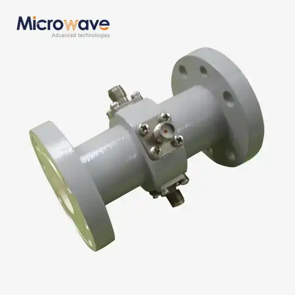 VIEW MOREWG Probe Coupler
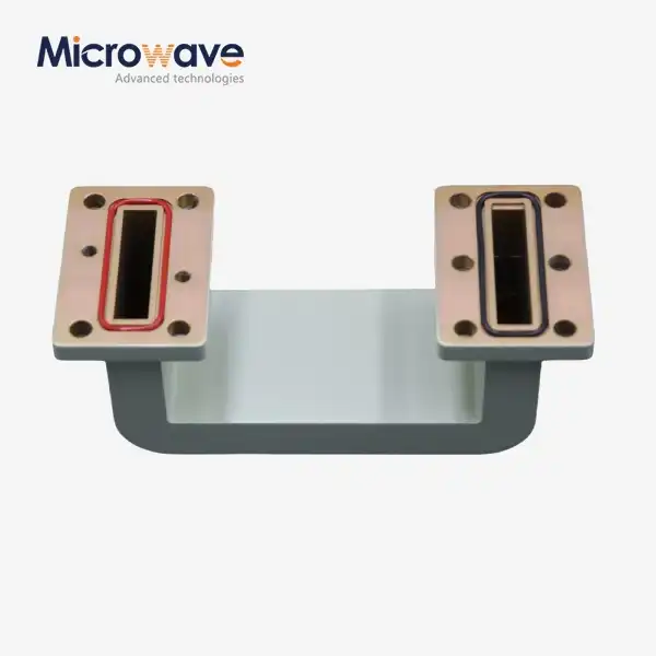 VIEW MOREDouble-bend Waveguide
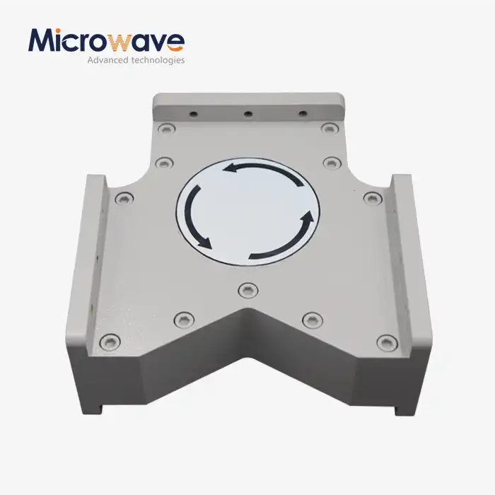 VIEW MOREHigh Power Waveguide Circulator
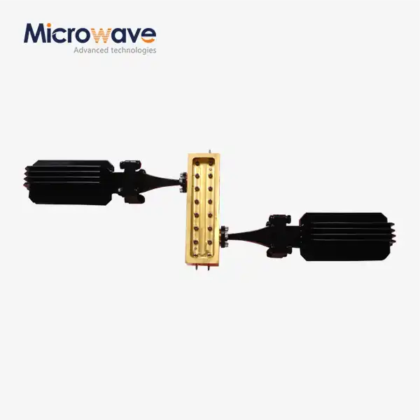 VIEW MOREWaveguide Coupling Fixed Attenuator
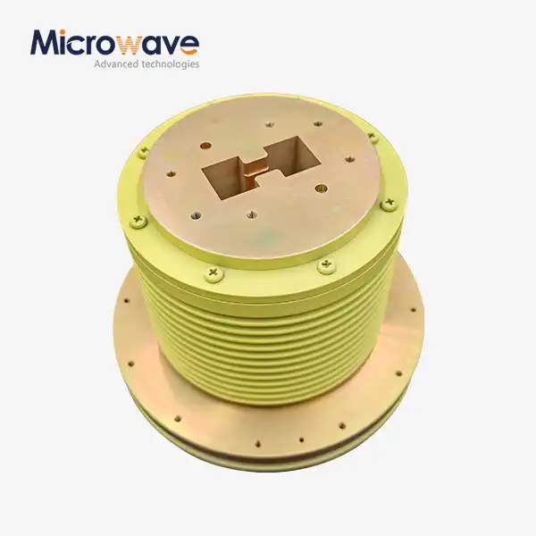 VIEW MOREDouble Ridge Waveguide Rotary Joint
 VIEW MOREWaveguide Adjustable Support
 VIEW MORELadder Membrane Square Dual Circular Polarization Horn Antenna
 VIEW MORELow Side Lobe Diagonal Linear Polarization Horn Antenna