





Why Does a Waveguide Flange Gasket Fail in High-Power Systems?
In high-power RF and microwave systems, a waveguide flange gasket does far more than seal two metal surfaces together. It maintains electromagnetic continuity, prevents pressurized waveguide leakage, and protects internal signal paths from moisture and contaminants. When this component fails, the consequences cascade quickly — elevated VSWR, unexpected insertion loss, thermal arcing, and, in mission-critical defense or satellite systems, full signal dropout. Understanding exactly why these failures occur is the first step toward preventing them.
Understanding Waveguide Flange Gasket Failures in High-Power Systems
A waveguide flange gasket has to work with two very strict requirements: tight tolerances for size and strong material performance. The microwave spectrum is not designed to work with regular gaskets. Waveguide-specific seals, on the other hand, need to keep the volume resistance below 0.005 ohm-cm and keep out compressed dry nitrogen or air, which is used to stop dielectric arcing inside the waveguide.
What Failure Actually Looks Like
Engineers often see waveguide flange gasket failure happening a long time before they can see a crack. Early warning signs include VSWR drifting over time, signal problems that happen from time to time during temperature changes, and measurable increases in insertion loss, which are most noticeable in high-frequency bands above 18 GHz. In sealed waveguide systems, even a small leak in the seal lets outside moisture in. This speeds up internal rust and makes it possible for the dielectric to break down when high-power loads are applied.
Root Causes of Waveguide Flange Gasket Failure in High-Power Systems
Usually, more than one failure mechanism works at the same time instead of separately. Thermal cycling is a constant enemy. For example, aerospace radar systems regularly go through cycles between -55°C and +125°C. Each cycle causes tiny strains to form in the elastomeric matrix. Over hundreds of cycles, this builds up into compression set, a permanent displacement that lowers the sealing contact force below the level needed to keep EMI protection working at over 100 dB.
Thermal Fatigue and Compression Set
When thermal and mechanical loads are applied for a long time, conductive elastomers, which are made up of silver-plated aluminum or copper particles mixed with a silicone or fluorosilicone binder, lose their ability to recover. When the compression set goes above about 25–30%, the waveguide flange gasket can't make enough contact pressure. This isn't a slight decrease; once the cutoff is passed, RF leakage can rise quickly.
Mechanical Stress from Improper Installation
Most installation mistakes happen because the bolts are over-torqued. When the bolt force is too high, the waveguide flange gasket material pushes into the waveguide opening and works as an iris, causing signal reflection and impedance mismatch. Under-torquing, on the other hand, creates tiny holes that let the EMI seal slip. The standard for conductive rubber materials, MIL-DTL-83528, says that the width should be compressed by 10 to 15 percent of its original size. It is designed so that standard widths like 0.027" and 0.032" can reach this range with the right power.
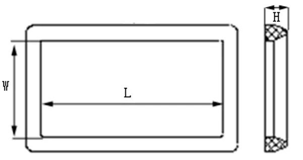
Material Incompatibility and Galvanic Corrosion
When different conductive materials touch aluminum flanges in wet or salty conditions, galvanic corrosion speeds up the surface degradation of the flanges. When water comes in contact with a silver-copper waveguide flange gasket attached to an aluminum flange, it creates an electrochemical potential, which is similar to a battery short-circuit. Navy and Marine system designers specifically ask for gaskets that are filled with silver-aluminum or nickel-graphite to eliminate this risk and extend the time between repair visits in harsh operating conditions.
How to Prevent Waveguide Flange Gasket Failures: Best Practices and Installation Guidelines
Failure can be avoided by making choices about the right materials, how to install them, and when to do maintenance all at the same time. There isn't just one thing that makes a difference; long-term dependability depends on paying careful attention to all three.
Here are the core preventive practices that engineering teams rely on:
- Match the binder to the chemical environment. Standard silicone works well in a wide range of temperatures. Silicone swells and loses its ability to carry electricity, so fluorosilicone is needed when the gasket will come into contact with jet fuel, hydraulic fluid, or industrial solvents.
- Verify dimensional accuracy before installation. Check with optical measuring tools to make sure that the gasket's internal hole lines up perfectly with the waveguide bore. Reflection can be measured even if something as small as a few thousandths of an inch gets in the way of the signal.
- Apply calibrated torque. Never go by how you feel. To make sure the compression is spread out evenly, use a torque wrench that is calibrated to the flange bolt standard and follow the cross-torque routine given by the flange maker.
- Replace, never reuse. Conductive elastomers keep their permanent deformation from the last compression cycle after a flange opening. When you reuse them, you create unknown holes in the insulation and the chance of pressure leaks.
If you follow these steps regularly, they will greatly cut down on unplanned downtime and protect your system investment throughout its operational lifecycle.
Inspection Intervals for High-Power Systems
High-power amplifier-fed waveguide runs, like those in SATCOM ground station uplinks, need to have their waveguide flange gaskets checked every time they are scheduled for maintenance, which is usually every 12 to 18 months when they are used all the time. Systems that work in places with a lot of vibration, like airborne radar platforms, do better with shorter gaps that match the repair rounds of the airframe.
Comparing Waveguide Flange Gaskets: Finding the Best Solution for High-Power Systems
Each of the three main types of gaskets fills a different performance gap. When you make the wrong choice, you introduce the same types of failure that a good choice is meant to stop.
Conductive elastomers with silver-aluminum filler can be used in most situations. They screen better than 100 dB from 10 MHz to 10 GHz, work with metal flanges without any problems, and are flexible enough to work with small surface imperfections. As a matter of fact, military radar, base station infrastructure, and industry RF systems all use them.
Metal gaskets, usually made of indium or soft copper, are better at keeping out air and heat at very high power levels, where flexible materials would get too hot. They need the surface of the flange to be almost perfectly flat and to be handled carefully so that the surface doesn't get damaged during assembly. They are mostly only used with waveguide sizes like WR-90 and WR-137 in emitter chain assemblies that are more than a few kilowatts.
PTFE-based composite gaskets with conductive filler are in the middle. They are not affected by chemicals and work well over a wide frequency range. They are especially useful in study and measurement settings where keeping the same size over test rounds is more important than getting the most shielding attenuation.
The total cost of ownership for all three types depends on how often they need to be replaced, how much it costs to install, and how much it costs to fix after a failure. This equation favors higher-specification materials in mission-critical platforms.
Procuring Waveguide Flange Gaskets for High-Power Applications
When buying precision RF sealing parts from other businesses, it's not just about comparing prices. Certifications like ISO 9001 and meeting the requirements of MIL-DTL-83528 show that the manufacturing process is consistent and that materials can be tracked back to their source. These requirements can't be changed when buying things for defense, space, and SATCOM.
Managing lead time is just as important. A lot of people who work on high-power systems keep a small supply of important waveguide flange gasket sizes on hand in case there are delays that could affect the mission. If a supplier lets engineering teams define the filler type, binder chemistry, and die-cut tolerances within ±0.005 inches, they can make the seal fit their exact flange shape instead of having to change an item from a catalog.
Conclusion
It is rare for a single thing to cause a waveguide flange gasket to fail in high-power systems. Thermal cycling, bad installation, mismatched materials, and exposure to the environment can all hurt the performance of a seal long before any damage can be seen. Getting rid of this problem requires careful choice of materials, careful installation, and planned repair plans. For procurement and engineering professionals, the most reliable way to keep a system running is to buy from a manufacturer with clear quality standards, the ability to track materials, and the ability to make changes to the system.
FAQ
Can a waveguide flange gasket be reused after a maintenance opening?
No, conductive elastomers have a fixed set of tension after being torqued. Reusing a squeezed gasket leads to uncertain EMI protection and the possibility of a pressure seal failing. As an industry best practice, every time a flange is taken apart, it must be replaced.
What temperature range can these gaskets typically withstand?
Most silicone-based conductive gaskets work well between -55°C and +125°C. Different types of fluorosilicone have similar ranges but are more resistant to fuels and acids. In very high-power transmitting systems, metal gaskets can handle higher peak temperatures.
What happens to the RF system when a gasket fails?
VSWR and insertion loss go up even if the seals only get slightly damaged. When moisture gets into pressure waveguide runs, it creates conditions for dielectric arcing to happen. When this happens, the waveguide flange gasket partially pushed into the hole can lead to a big impedance mismatch, which stops signals from traveling through the waveguide section that is affected.
How does gasket thickness affect signal performance?
Although thicker waveguide flange gaskets can better handle uneven surfaces, they also lengthen the electrical path and raise the risk of compression blowout. Standard widths are designed to achieve the best compression deflection of 10–15%, which balances the purity of the signal route with the trustworthiness of the seal.
Partner with ADM for Reliable Waveguide Flange Gasket Solutions
Every part that ADM makes is based on more than 20 years of experience making precise microwave parts. We are a reliable provider of waveguide flange gaskets to the defense, aerospace, and satellite communication industries around the world. Our quality is ISO 9001-certified, and we can trace materials back to MIL standards. We also offer full OEM personalization. You can email our tech team at craig@admicrowave.com to get samples or a custom price.
References
1. IEEE Transactions on Microwave Theory and Techniques — 2019
2. MIL-DTL-83528: Performance Specification, Gaskets, Sealing, Conductive Elastomer — U.S. Department of Defense, 2017
3. Microwave Engineering — David M. Pozar, Wiley, 2011
4. IEEE Standard for Measuring the Effectiveness of Electromagnetic Shielding Enclosures (IEEE Std 299) — IEEE, 2006
5. Journal of Electronic Packaging, ASME Transactions — 2020
6. Handbook of Microwave Technology, Volume 1: Components and Devices — Tatsuo Itoh et al., Academic Press, 1995
YOU MAY LIKE
 VIEW MOREMicrowave Fixed Attenuator
 VIEW MORECircular Straight Waveguide
 VIEW MOREWaveguide Miter Bend
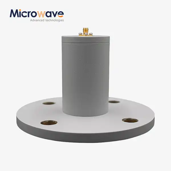 VIEW MORECircular Waveguide To Coaxial Adapter
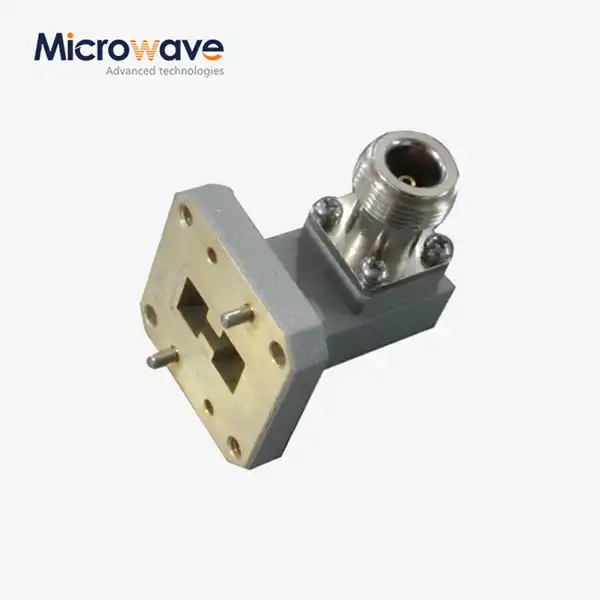 VIEW MORERight Angle Double Ridged WG To Coaxial Adapter
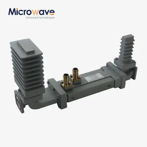 VIEW MOREHigh Power Waveguide Differential Phase Shift Isolator
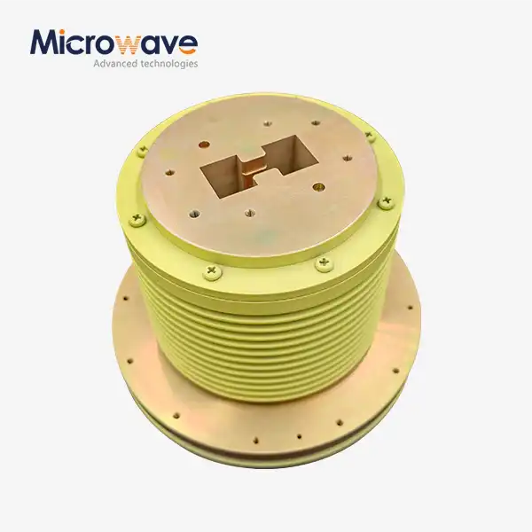 VIEW MOREDouble Ridge Waveguide Rotary Joint
 VIEW MOREUltra Double-ridged Horn Antenna
