Why Do Waveguide Attenuators Outperform Coaxial Above 40 GHz?
When engineers push signal frequencies past the 40 GHz threshold, the choice of attenuation technology stops being a preference and starts being a critical engineering decision. Waveguide attenuators consistently outperform their coaxial counterparts at millimeter-wave frequencies because their hollow metallic structure eliminates the dielectric losses and skin-effect degradation that plague coaxial designs. Above 40 GHz, coaxial lines suffer mounting insertion loss, reduced power handling, and signal integrity issues that compound rapidly with frequency. Waveguide attenuators sidestep these limitations entirely, delivering cleaner attenuation, tighter VSWR control, and far greater reliability in demanding environments like radar, satellite uplinks, and 5G mmWave test systems.
Understanding Waveguide and Coaxial Attenuators
What Sets These Two Technologies Apart
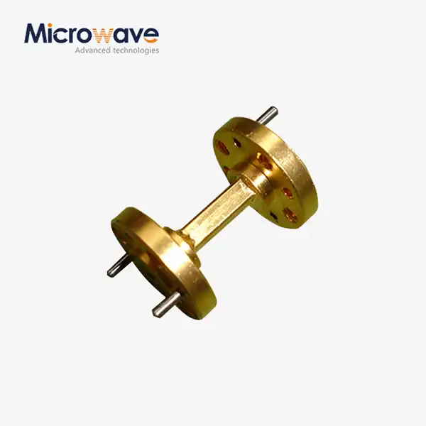
An electromagnetic wave passes through a coaxial attenuator that has a center wire, a dielectric material around it, and an outer cover. Above 40 GHz, that insulating material starts to be a problem because it takes energy and causes loss that rises with frequency. A waveguide attenuator, on the other hand, moves electromagnetic waves through a metal tube that is hollow and doesn't have any dielectric filling inside it. The main TE₁₀ mode moves with very little loss because the path it takes is made up of air, which is basically a vacuum.
This difference in structure has effects in the real world. Engineers often choose rectangular waveguide components for aerospace signal testing, radar transmit-receive modules, and Ka-band satellite ground stations. This is because dielectric-free propagation keeps the signal integrity intact, while coaxial solutions would cause noise floors and power loss that are unacceptable.
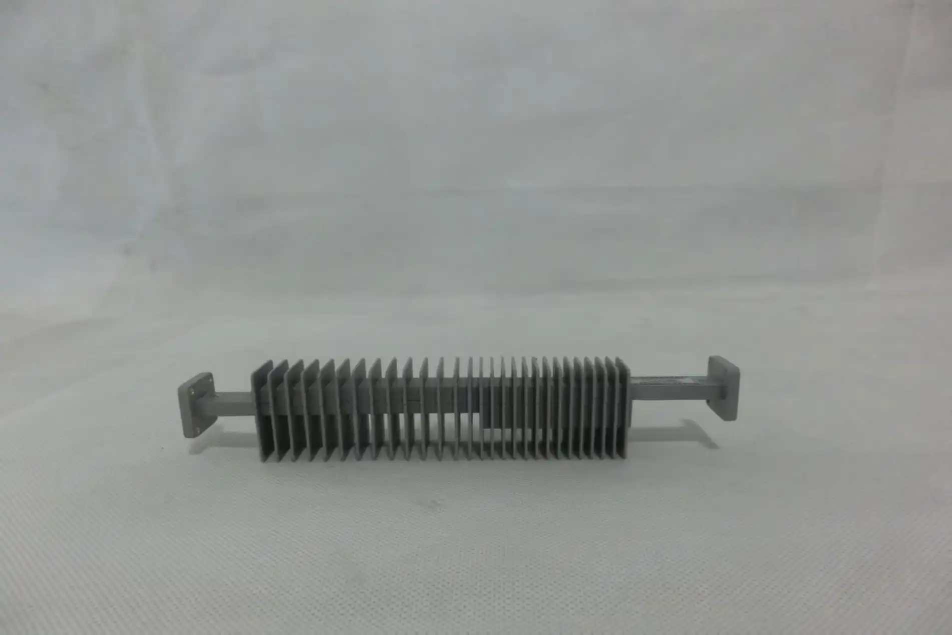
Key Technical Advantages of Waveguide Attenuators Above 40 GHz
Lower Insertion Loss and Higher Power Tolerance
Once you go over 40 GHz, you can see and feel the difference in performance between these two groups of parts. What are the main technical benefits of waveguide designs that make them the best choice for high-frequency settings?
- Reduced insertion loss: In the W-band (75–110 GHz), rectangular waveguides usually have insertion loss below 0.1 dB per inch, while coaxial assemblies at the same frequencies can have loss levels above 1–2 dB per inch. This is a direct difference that lowers the system noise figure and dynamic range in receiver chains that are sensitive to it.
- Superior power handling: Waveguide structures can handle normal power levels in the kilowatt range at millimeter-wave frequencies. Coaxial connectors, such as 1.0 mm or 0.8 mm types, can only handle a few watts before they start to break down. These are the only options above 40 GHz.
- Minimal VSWR: In a well-machined waveguide cavity, reflections are low because there are no sudden changes in resistance. Precision-machined waveguide attenuators usually get VSWR values of 1.05:1 or better, which keeps the match integrity across the whole waveguide band.
- Thermal stability: In continuous-wave radar and satellite payload uses, resistive coaxial attenuators can lose or gain 0.5 to 1 dB of their measured attenuation values over time due to temperature changes. The thermal coefficients of waveguide designs that use resistive card or vane attenuation elements are much easier to predict.
These benefits directly lead to gains at the system level. A procurement engineer who is looking for parts for a 77 GHz automotive radar testbed or an E-band point-to-point radio will find that the performance of a waveguide attenuator lowers the cost of calibration and replacement frequency, and in the end gives a better total cost of ownership, even though it costs more per unit.
Comparative Analysis: Waveguide vs. Coaxial Attenuators for Microwave Applications
Fixed vs. Variable Configurations and B2B Procurement Factors
There are fixed and variable versions of both waveguide and coaxial attenuators, but as frequency goes up, their relative value changes a lot. Precision resistive-card designs for fixed waveguide attenuators provide the highest level of stability and repeatability for calibration labs and automated test equipment that works above 40 GHz. Variable waveguide attenuators, which usually work with rotary vane or sliding-screw mechanisms, let you make changes all the time without the loss of quality that comes with coaxial pads that are made in the style of a mechanical potentiometer at millimeter-wave frequencies.
When it comes to buying, waveguide attenuators are more expensive per unit than coaxial pads that do the same thing. Custom waveguide flanges, such as CPR, UBR, or customer-specific interfaces, can take anywhere from four to twelve weeks to make, based on how hard they are to machine and how they need to be finished. Still, buying workers who look at the total cost of a program always say that the extra cost is worth it because the system is down less often, needs to be calibrated less often, and fails less often on average.
Reliable global companies with well-known waveguide product lines sell stock parts for common bands like Q-band (33–50 GHz), V-band (50–75 GHz), and W-band (75–110 GHz). Engaging suppliers with in-house machining, plating, and RF test capabilities ensures better quality documentation and tighter control of tolerances, which are very important in defense and aerospace supply chains.
How to Select the Right Waveguide Attenuator for Your High-Frequency Needs
Key Specification Parameters to Evaluate
To choose the right component, you need to make sure that a number of interdependent factors match the design of your system. Here are the parts of the specification that need to be carefully looked over:
- Frequency band and waveguide size: Make sure that the standard waveguide designation (WR-22 for W-band, WR-28 for Ka-band, etc.) lines up with the system flanges that are already there to avoid making extra connections.
- Attenuation value and flatness: Fixed waveguide attenuators are measured in decibels (dB), and there is a range of smoothness that can be used across all bands. A 10 dB pad with a flatness rating of ±0.5 dB across 75–110 GHz works very differently in a calibrated receiver chain than one with a rating of ±1.5 dB.
- Power rating: Check both the peak and average power rates. Pulsed radar uses put a lot of power on attenuator vane elements all at once, even when the average power is low.
- VSWR specification: A VSWR greater than 1.15:1 increases the chance of measurement error and jitter when used for low-noise amplifier (LNA) input safety or signal generator output padding.
Once the technical standard is confirmed, it is helpful for the buying process to ask for full test data files, check the state of MIL-spec or a similar certification, and see how quickly the seller responds to requests for custom flange setups. As part of every sourcing agreement for ongoing production projects, you should talk about bulk order prices and write down shipping wait times.
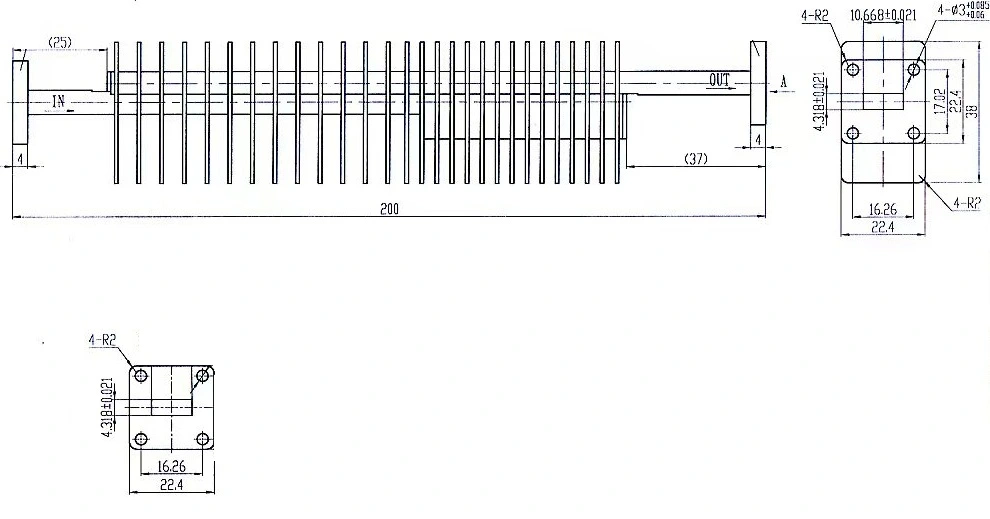
Future Trends & Innovations in High-Frequency Attenuator Technology
Materials, 5G, and OEM Collaboration Driving Innovation
Attenuators for millimeter waves are at a turning point in the market. 5G mmWave infrastructure, next-generation phased-array radar, and low-Earth orbit (LEO) satellite constellations are all putting pressure on manufacturers to make parts with more instantaneous bandwidth, smaller physical footprints, and better temperature compensation.
New materials are being made, like silicon carbide (SiC) plates for resistive elements and gold-plated metal housings that can fit parts more precisely. Because of these improvements, attenuation accuracy can now reach levels that could only be reached with laboratory-grade equipment before. At the same time, OEM co-design agreements are becoming the norm. More and more, system integrators work directly with waveguide component makers to make attenuator-switch-transition assemblies that work as a single unit. This cuts down on the number of connections between parts and makes the whole subsystem more reliable. As the complexity of mmWave systems continues to rise, procurement professionals who build these collaborative relationships with suppliers now will have a clear advantage when it comes to sourcing.
Conclusion
Above 40 GHz, the way electromagnetic waves travel makes waveguide technology the clear winner. Because they don't lose insulation, can handle high power levels, and keep signals pure across wide millimeter-wave bands, waveguide attenuators are the best choice for engineering in aerospace, defense, satellite, and advanced telecommunications industries. The reliability and performance of tomorrow's high-frequency systems will depend on the purchasing choices made today, like choosing trusted makers, setting up customization relationships, and choosing parts with tested data.
FAQ
What frequency range suits waveguide attenuators best?
Above 40 GHz, where coaxial dielectric loss becomes expensive, waveguide attenuators show their greatest performance edge.
What is the difference between fixed and variable waveguide attenuators?
Because they are stable and regulated, fixed types are great for signal conditioning and noise figure checking. Variable types, like rotary vane or sliding-screw designs, can be changed at any time, which makes them useful for dynamic test sets and controlling power transmission.
How does waveguide size relate to operating frequency?
A different frequency band is assigned to each waveguide designation (WR-28, WR-22, WR-15, etc.). Smaller cross-sections allow higher millimeter-wave bands, while larger waveguides handle lower frequencies. It is important that the size of the waveguide matches the frequency band of your system.
Can waveguide attenuators be customized for non-standard flanges?
Yes, reputable manufacturers often make custom flange interfaces, non-standard attenuation values, and housing materials that aren't found in other products in order to meet the needs of specific programs, like those for defense and satellite payload integration.
Partner with ADM for Precision Waveguide Attenuator Solutions
ADM offers engineered waveguide attenuators for frequencies in the Q, V, and W bands. These come with verified RF test results and quick expert help. As a trusted waveguide attenuator manufacturer, ADM uses precise cutting, in-house testing, and easy modification to meet your exact millimeter-wave needs. To get specs, bulk prices, or a proposal on a custom design, you can email the ADM team at craig@admicrowave.com.
References
1. Pozar, D. M. — Microwave Engineering, 4th Edition, Wiley, 2011.
2. Collin, R. E. — Foundations for Microwave Engineering, 2nd Edition, IEEE Press, 2001.
3. IEEE Transactions on Microwave Theory and Techniques — "Loss Characteristics of Millimeter-Wave Waveguide Components," IEEE MTT-S, 2019.
4. Microwave Journal — "Advances in Millimeter-Wave Passive Components for 5G and Radar," Horizon House Publications, 2022.
5. Montgomery, C. G., Dicke, R. H., & Purcell, E. M. — Principles of Microwave Circuits, MIT Radiation Laboratory Series, McGraw-Hill, 1948 (reissued by IET, 2009).
6. IEEE Spectrum — "The Millimeter-Wave Frontier: Components Enabling Next-Generation Wireless," IEEE, 2021.