





How to Choose the Right Waveguide Fixed Attenuator for Your Band?
Choosing the right waveguide fixed attenuator starts with knowing your operating frequency band and what your system actually demands. These passive microwave components reduce signal power by a fixed dB value without distorting the waveform or phase — making them indispensable in radar, SATCOM, and mmWave test environments. To select correctly, you need to match the EIA waveguide size (e.g., WR-90 for X-Band, WR-28 for Ka-Band) to your frequency range, then evaluate attenuation accuracy, VSWR, power handling, and flange type. Getting this right protects sensitive components and preserves signal integrity across your entire RF chain.
Understanding Waveguide Fixed Attenuators: Basics and Key Specifications
What They Are and How They Work
A waveguide fixed attenuator is a precise passive part that puts a resistive element directly into the electric field of the waveguide. This resistive element is usually a lossy dielectric vane or wedge. This takes in RF energy and turns it into heat, which lowers the signal's amplitude by a certain number of decibels. Waveguide versions work better than coaxial attenuators at millimeter-wave frequencies, with more stable structures and less variation in insertion loss across a wider range of frequencies.
Key Electrical Specifications to Know
Before buying something, knowing the main factors stops mistakes that cost a lot of money:
- Attenuation accuracy typically ranges between ±0.3 dB and ±1.0 dB if you change the total attenuation value. Flatness of ±0.2 dB across the band is achieved by metrology-grade units.
- VSWR (Voltage Standing Wave Ratio) should stay below 1.20:1 for most uses. High-precision models aim for VSWR < 1.10:1 to cut down on reflections that could harm sources further upstream.
- Average and peak power handling define limits on temperature and voltage. It's not just heat capacity that limits peak power; arcing risk within the waveguide design also plays a role.
- Frequency range is directly affected by the size of the waveguide. The WR-90 covers the X-Band (8.2–12.4 GHz), the WR-28 covers the Ka-Band (26.5–40 GHz), and the WR-10 covers the W-Band (75–110 GHz).
Together, these factors show whether a part will work correctly or cause measurement mistakes and system instability over time.
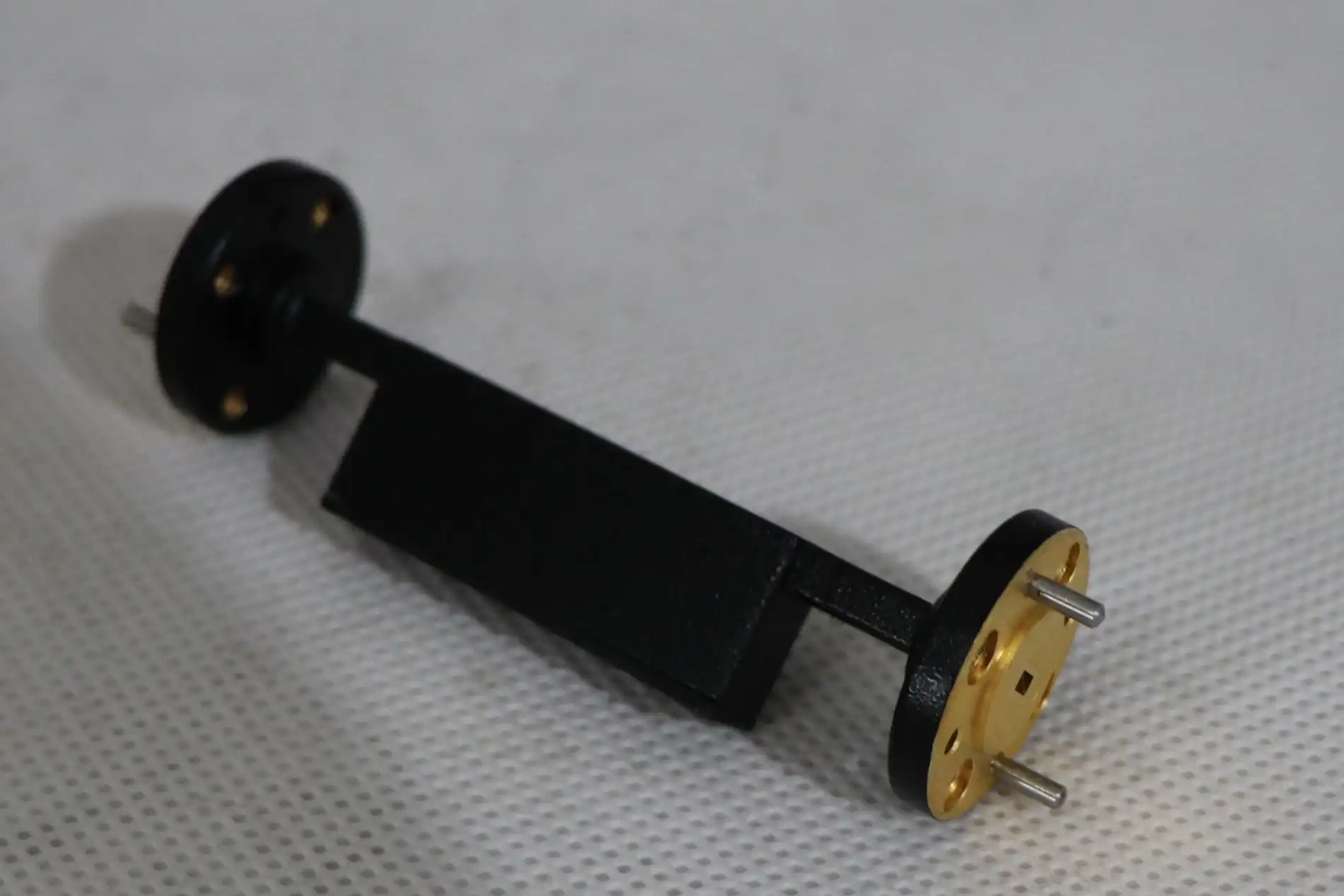
Core Criteria to Evaluate When Choosing a Waveguide Fixed Attenuator
Matching Frequency Band and Waveguide Size
You can't choose the wrong waveguide size; if the sizes don't match, the signal will be cut off or unwanted higher-order modes will spread. Always start with your center frequency and check that the EIA standard waveguide name matches. WR-90 is needed for an X-Band radar device, and WR-28 is needed for a 5G mmWave test bench that works at 28 GHz. This one factor narrows down the products you can choose from a lot before you even start comparing them.
Power Handling, Thermal Management, and Flange Compatibility
For high-power uses like SATCOM uplink chains or defense radar transmit/receive modules, waveguide fixed attenuators must be rated for both continuous wave (CW) and peak power. These are the most important thermal and physical factors to look at:
- Material construction — High-quality units are made from Oxygen-Free Copper (OFC), Aluminum 6061, or Brass that has been plated with silver or gold to stop skin-effect losses and corrosion in harsh environments.
- Thermal stability — Absorber materials that are thermally stable, such as Silicon Carbide or special ferrite ceramics, keep attenuation levels at or below 0.005 dB/°C, which is necessary for high-power continuous-wave operation.
- Flange type — The UBR, CPR, and FBP flange configurations must perfectly line up with the waveguide assembly you already have to avoid mating loss and mechanical stress.
By checking these things before you buy, you can avoid integration problems afterward, which are hard to fix in production settings and cost a lot of money and time.
Fixed vs. Variable vs. Pad Attenuators
Fixed attenuators provide stable, repeatable attenuation without any change in methods. They are perfect for constant signal conditioning in production systems. Variable attenuators are flexible, but over time they cause mechanical wear and phase problems. Pad attenuators help with VSWR when two parts don't match, but they might not work well in high-power settings. Long-term, fixed waveguide attenuators are still the most reliable and cost-effective choice for most OEM and military purchase situations.
Comparing Leading Waveguide Fixed Attenuator Solutions in the Market
Brands like Pasternack, Maury Microwave, Werlatone, and American Microwave Corporation are well-known in the RF and microwave component market. Each brand is aimed at a different group of applications.
Pasternack is known for having a large catalog and quick shipping on standard waveguide bands. This makes it a good choice for engineers and wholesalers who need ready-to-use options. Maury Microwave has a great reputation for making high-precision calibration and metrology-grade parts that need to be flat in terms of attenuation and VSWR performance. Werlatone specializes in high-power designs, and its products are rated for kilowatt-level CW power, making them a great choice for people who build radar and EW systems.
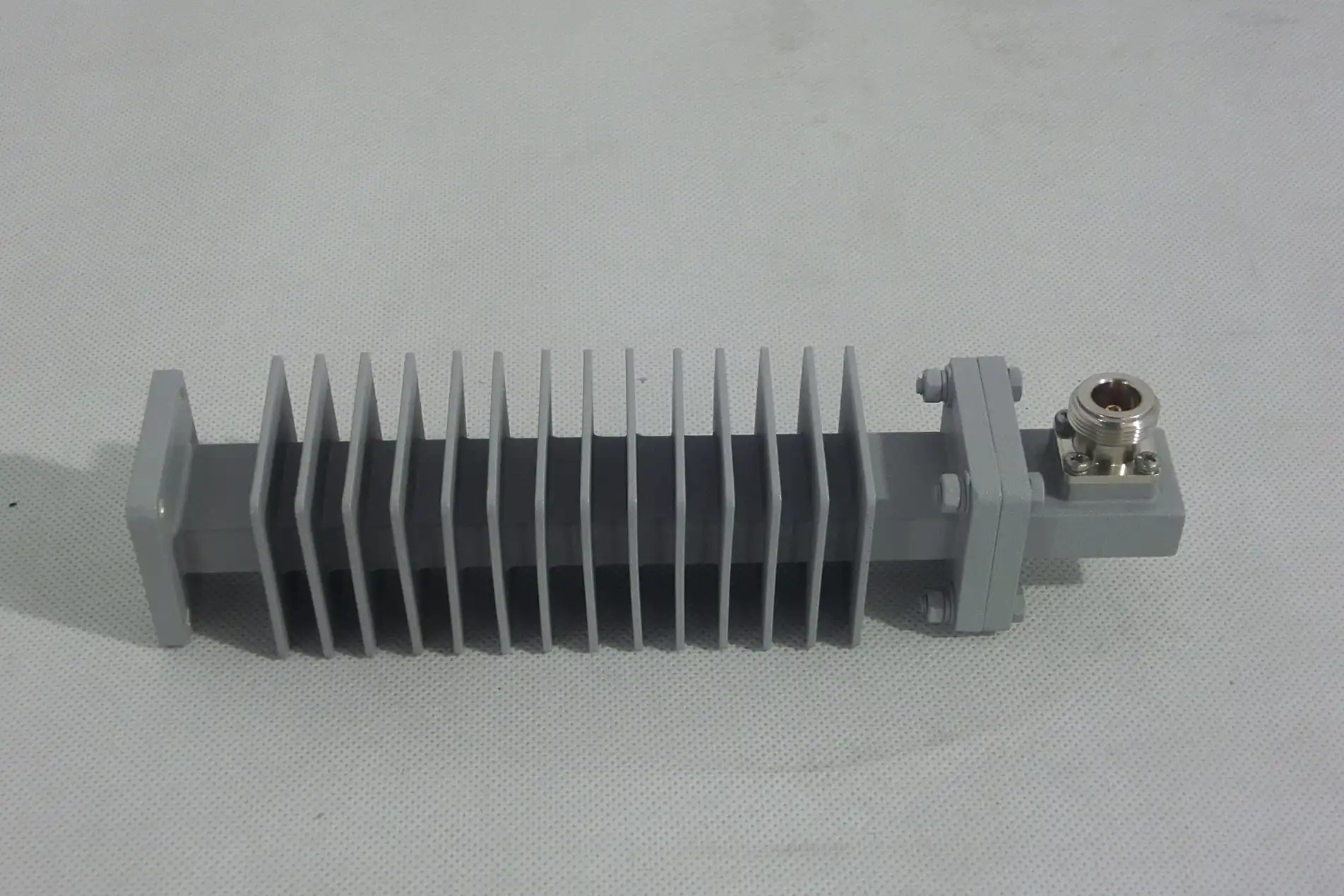
When looking at choices for buying in bulk from other businesses, wait time, the ability to make things to order, and compliance with MIL-DTL-3933 are just as important as the raw electrical performance for a waveguide fixed attenuator. System-level integration costs can be cut by a large amount when non-standard frequency bands or unique flange configurations are taken into account in custom designs. To make sure that performance claims are true, you should always ask for calibrated test data and documents that can be tracked along with any purchase price.
Procurement Best Practices: How to Purchase Waveguide Fixed Attenuators Efficiently
It takes more than just comparing datasheets to find waveguide fixed attenuators that work well. For important tasks, making sure that suppliers have the right credentials, that quality standards are met, and that wait times are communicated clearly all affect how the procurement process goes.
Prices change depending on the frequency band, power level, finish of the material, and the number of units being made. Because they are made with more precise tolerances and special absorber materials, Ka-Band and W-Band units are more expensive than their X-Band counterparts. When negotiating bulk orders, it's best to ask for tiered pricing structures and make sure you know the minimum order quantities right away to avoid delays.
When it comes to defense and SATCOM projects, where schedule delays have huge cost effects, inventory planning is very important. Supply chain risk can be greatly reduced by working with suppliers who offer flexible manufacturing and safety stock programs. Before committing to full production quantities, you should always use datasheets, S-parameter files, and application engineering help to make sure that the standards you bought match the needs of the system.
Conclusion
It is a structured, specification-driven process to choose the right waveguide fixed attenuator. It is possible to tell if a component works as it should by matching the waveguide size to the frequency band, checking the accuracy of the VSWR and attenuation, making sure the component can handle power and heat, and making sure the flanges are compatible. The success of a project depends on more than just technical fit. It also depends on how well the seller is trusted, how well wait times are managed, and how well the bulk buying strategy works. Spending time on an in-depth analysis up front keeps systems from breaking down in the future, which saves money and makes the supply chain stronger over time.
FAQ
How does a waveguide fixed attenuator differ from a coaxial attenuator?
Waveguide fixed attenuators work at much higher frequencies (usually above 8 GHz) and have better power handling and less insertion loss than coaxial versions. They do this by using hollow metallic transmission lines. Coaxial attenuators are more flexible at lower frequencies, but they don't work as well at mmWave bands.
How do I determine my insertion loss and return loss requirements?
Set your system link budget and receiver sensitivity as a first step. Insertion loss shouldn't lower SNR below acceptable levels, and return loss (which is related to VSWR) should stay high enough to keep reflections from making the source unstable. Return loss of more than 20 dB (VSWR < 1.22:1) is what most system designers aim for.
Are custom frequency band attenuators available?
Yes. By changing the waveguide dimensions, absorber geometry, and flange configurations, manufacturers can make attenuators for bands that aren't standard. Lead times and minimum amounts are usually longer for custom orders.
Can these attenuators handle bidirectional signal flow?
Most waveguide fixed attenuators are symmetric and can be used in both directions. In situations with a lot of power, make sure that the thermal design allows heat to escape from the port that gets the main RF input.
What standards apply to mil-spec waveguide attenuators?
The main U.S. military standard for fixed attenuators is MIL-DTL-3933, which covers performance, environmental toughness, and marking requirements.
Partner with ADM for Your Waveguide Fixed Attenuator Supply Needs
ADM sells approved, high-performance waveguide fixed attenuators in X-Band, Ku-Band, Ka-Band, and W-Band for use in defense, SATCOM, and precision test applications around the world. As a reliable supplier of waveguide fixed attenuators, ADM offers a wide range of buying options, such as custom designs, bulk pricing, and fast shipping around the world. For datasheets, S-parameter files, and affordable quotes, please get in touch with our tech team directly. Reach us at craig@admicrowave.com to browse available inventory and request a consultation today.
References
1. Pozar, D. M. — Microwave Engineering, 4th Edition. Wiley, 2011.
2. IEEE Transactions on Microwave Theory and Techniques — Passive Component Characterization at Millimeter-Wave Frequencies. IEEE, 2019.
3. Collin, R. E. — Foundations for Microwave Engineering, 2nd Edition. IEEE Press/Wiley, 2001.
4. MIL-DTL-3933 — Fixed Attenuators, Radio Frequency: General Specification. U.S. Department of Defense, 2004.
5. Wadell, B. C. — Transmission Line Design Handbook. Artech House, 1991.
6. Rizzi, P. A. — Microwave Engineering: Passive Circuits. Prentice Hall, 1988.
YOU MAY LIKE
 VIEW MORECustom WG to Coaxial Adapter
 VIEW MOREBroadwall Directional Coupler
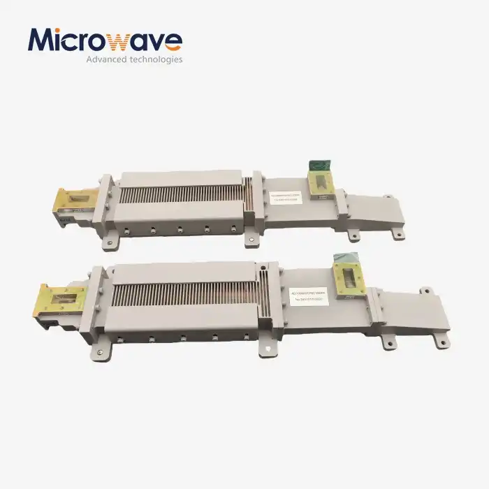 VIEW MOREWG Circulator
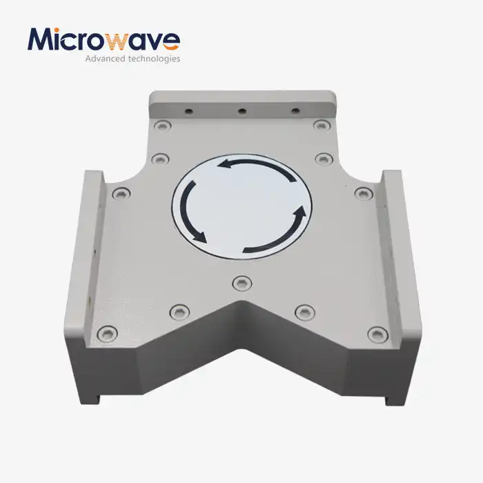 VIEW MOREHigh Power Waveguide Circulator
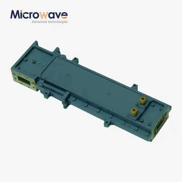 VIEW MOREHigh Power Waveguide Differential Phase Shift Circulator
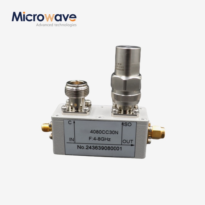 VIEW MORECoaxial Directional Coupler
 VIEW MOREStandard Horn Antenna
 VIEW MOREConical Horn Lens Antenna
