





What Freq Range Should a Coaxial Variable Attenuator Cover?
In mission-critical RF and microwave uses, picking the right frequency range for a coaxial variable attenuator has a direct effect on how well the system works. For lower-frequency uses, coaxial variable attenuators usually cover ranges from DC to 1 GHz. For mid-band communications, they cover ranges from 1 GHz to 6 GHz. Above 6 GHz, they often go up to 18 GHz or 40 GHz for aerospace, defense, and satellite systems. The best frequency coverage depends on the needs of your application, such as the amount of bandwidth needed, the level of signal integrity that can be tolerated, and how well it can be integrated with existing transmission infrastructure. Making sure that the frequency range fits your needs perfectly is the best way to get the best insertion loss, VSWR performance, and measurement accuracy.
Introduction
In the tough RF and microwave environments of today, coaxial variable attenuators are essential for controlling signals and keeping the system safe. These precise parts are necessary for testing labs, satellite ground stations, radar calibration sets, and telecoms infrastructure because they let engineers change the amplitude of a signal without changing the shape or frequency content.
Picking the right frequency band is not an easy choice to make. It changes all of the attenuator's functions, from insertion loss and return loss to how it handles power and how stable it is over time. Defense contractors, satellite service providers, and research institutions all have purchasing managers who have to deal with technical specifications as well as supply chain issues like lead times, the ability to customize products, and compliance certifications such as ISO 9001 and RoHS.
We at Advanced Microwave Technologies Co., Ltd. know that global B2B buyers are under more and more pressure to choose parts that are both technically accurate and easy to get. Thanks to our many years of experience, we can help purchasing engineers, original equipment manufacturers (OEMs), and system integrators choose the right frequency range for their devices while also staying within their budgets. This article gives you a complete plan to help you choose the best attenuator for frequency coverage on your next purchase.
Understanding Coaxial Variable Attenuators and Frequency Range Fundamentals
How do coaxial variable attenuators function?
A coaxial variable attenuator lowers the intensity of an RF signal without changing its phase or adding a lot of harmonic distortion. It does this by adding controlled resistive loss to the signal line. Fixed attenuators have a single attenuation value, while step attenuators change loss in discrete steps. Variable models, on the other hand, can be adjusted continuously, either by hand using micrometer knobs or electronically through control interfaces.
Frequency Range Impact on Performance Parameters
The frequency range has a direct effect on the features of insertion loss and return loss. At lower frequencies, parasitic effects aren't very strong, so attenuators can keep their response curves flat. As the operating frequencies rise into the microwave and millimeter-wave range, parasitic capacitance and inductance become more noticeable. This could make accuracy worse and cause ripples that change with frequency. By carefully designing resistive elements and making sure connection contacts are precise, high-quality devices keep these differences to a minimum.
Common Frequency Band Categories
Knowing the standard frequency classifications used in your industry can help you put your application needs in context. Low-band attenuators work with old communication systems, industrial measurement setups, and basic RF testing environments. They can handle frequencies from DC to 1 GHz. The mid-band range, from 1 GHz to 6 GHz, covers current wireless standards like LTE and lower 5G bands for smartphones. High-frequency coaxial variable attenuators that work above 6 GHz—up to 18 GHz, 26.5 GHz, or even 40 GHz—help with millimeter-wave research, advanced radar systems, and satellite communications, where keeping the signal strong at very high frequencies is very important.
Key Technical Specifications Related to Frequency Range
Frequency Range and Power Handling Interplay
As frequency goes up, skin effect losses and higher thermal stress on resistive elements make it harder for them to handle power. A coaxial variable attenuator that can handle 2 watts at 1 GHz might only be able to handle 0.5 watts at 18 GHz. Because of this, procurement teams have to carefully match power ratings with operational scenarios. For example, testing transmitters needs a higher power tolerance than measuring receiver sensitivity. When you go over the rated power, the resistive element breaks down. This changes the attenuation values permanently and could lead to a catastrophic failure.
Insertion Loss and VSWR Across Frequency Bands
Insertion loss is the signal loss that happens when the reduction is set to its lowest level, which is usually 0 dB. Quality devices keep insertion loss below 0.5 dB over the frequency range they are designed for, which protects system link budgets. The voltage standing wave ratio (VSWR) measures how well the impedance matches. Values below 1.3:1 mean that the matching is excellent, preventing reflections that could affect the accuracy of the measurement. Both factors change with frequency, so datasheets should list these measurements at a number of different frequency points across the working range.
Interpreting Datasheets for Frequency-Specific Metrics
The buying and engineering teams should carefully read the datasheets to find information about frequency flatness. This is usually shown as a change in attenuation over the frequency range (±1.0 dB at 18 GHz, for example). This measure shows how well the device stays true to its set attenuation values across its entire bandwidth. Also, check the types of connections. SMA connectors can usually handle frequencies up to 18 GHz, while 2.92 mm and K connectors can handle frequencies up to 40 GHz. By matching the connector's specs to your frequency needs, you can avoid problems with interface compatibility and measurement mistakes.
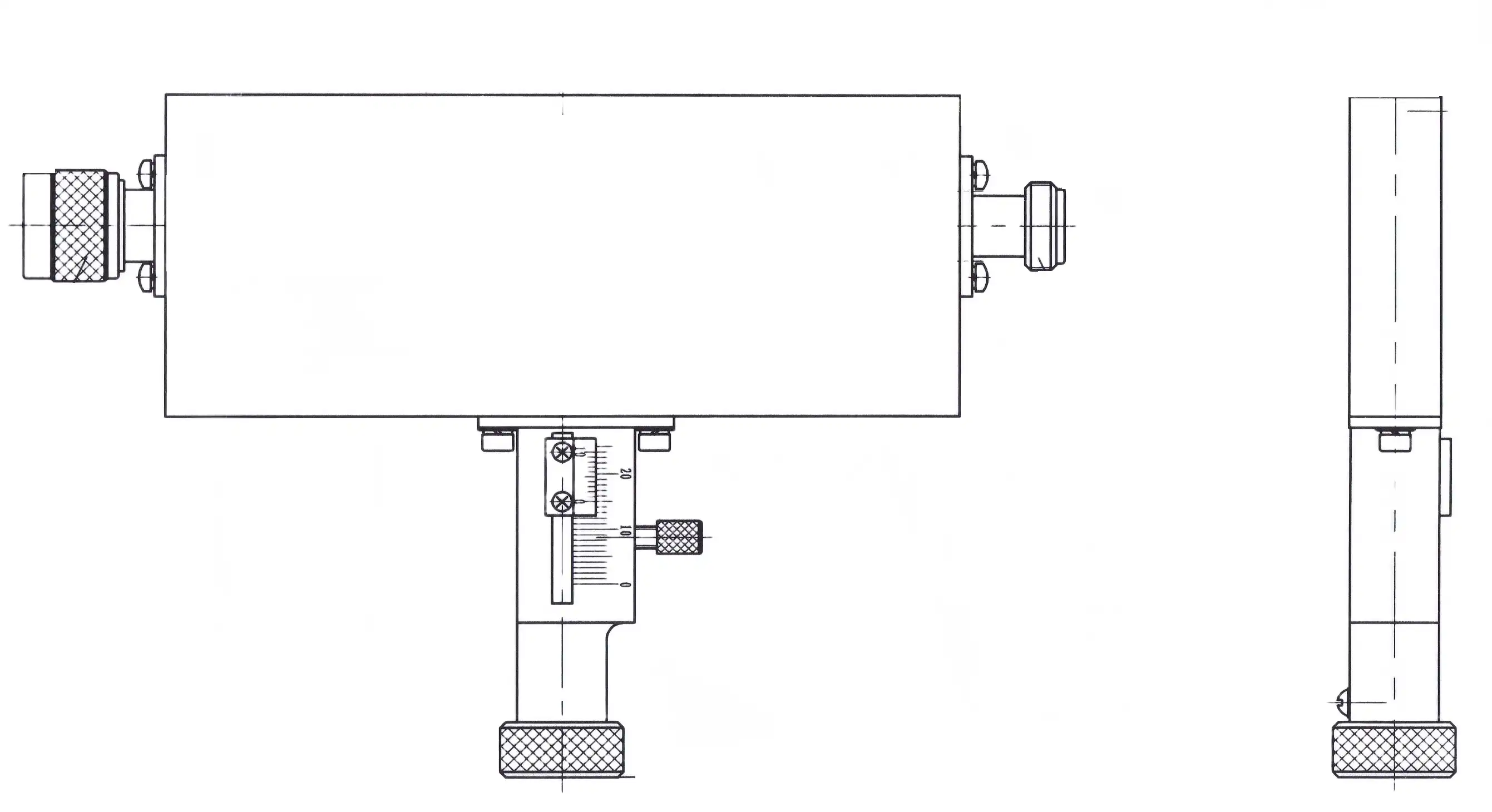
How to Choose the Right Frequency Range for Your Attenuator: A Decision Support Approach?
Application-Specific Frequency Requirements
Frequency coverage needs are different for each application. RF testing labs that check out cellular base stations need coverage from 0.7 GHz to 6 GHz so they can test for a number of different wireless standards. For defense and aerospace radar testing, X-band coverage (8 GHz to 12 GHz) or wider bands up to 18 GHz is often needed. Satellite base station technology might need Ku-band (12 GHz to 18 GHz) or Ka-band extension above 26 GHz. By matching your system's operational bandwidth to the frequency coverage of an attenuator, you can be sure that the two will work together smoothly, with no performance gaps.
Essential Selection Criteria
Check the attenuation range as well as the frequency coverage of the coaxial variable attenuator. Typical ranges are 0 to 60 dB or 0 to 90 dB, with resolution determining how precisely the change is made. Continuous variable models have an infinite range of resolution, which makes them perfect for fine-tuning analog circuits. Step attenuators offer better repeatability and numerical accuracy, which is very important in automatic test settings where measurement accuracy drives output. The level of accuracy needed also plays a role in the choice. For example, research applications might need 0.25 dB accuracy, while field deployment scenarios might be okay with 0.5 dB variation.
Supplier Matching Considerations
To find suppliers who can meet your frequency needs, you need to look at their minimum order quantities, lead times, and ability to customize. It usually takes two to four weeks to ship catalog items, but eight to twelve weeks for custom designs that include certain frequency ranges, connector types, or power ratings. Suppliers with strong technical support can suggest the best setups, offer alternative solutions when specs don't match up, and provide a lot of test data to prove frequency performance. Building relationships with manufacturers who offer flexible MOQ terms makes both the prototype development and mass production phases easier.
Comparing Coaxial Variable Attenuators with Different Frequency Ranges: Market Insights
Benefits and Trade-offs of Wide Frequency Coverage
Wide-band attenuators that work from DC to 18 GHz are very flexible, so one device can be used for many test situations. This makes inventory management easier. This method works well for labs working on a variety of projects or system integrators building platforms for multi-band communication. But broadband designs often come with trade-offs. For example, insertion loss may be slightly higher than in narrowband designs, and the physical size and complexity of the connectors may increase. Also, devices with wider frequency coverage usually cost more, so narrowband devices are a good deal when applications need to work within limited frequency windows.
Industry Case Studies Demonstrating Frequency Selection
A big company that makes telecom equipment recently decided to use only 1 GHz to 6 GHz variable attenuators for testing 5G small cells in production. This saved them 30% of the cost of using multiple devices before. The frequency range they were going for perfectly matched their sub-6 GHz product line while still meeting the tight insertion loss requirements needed for automated test equipment integration.
Different things are needed for different aerospace validation programs. A defense firm working on the next generation of phased array radars asked for DC to 18 GHz attenuators, even though they mostly work in the X-band range. The wider range allowed for harmonic readings and future system upgrades without having to redesign any parts. This shows that planning ahead during buying saves money by avoiding expensive changes in the middle of a project.
When OEMs put attenuators into satellite communication systems, they usually choose devices that work only in the Ku band (10 GHz to 18 GHz). In space-to-ground communications, where every tenth of a decibel affects system performance and maintenance costs, this narrowband method keeps link margin as high as possible by minimizing insertion loss.
Procurement Best Practices for Coaxial Variable Attenuators Covering Your Desired Frequency Range
Finding the right balance between technical requirements and business realities is key to successful procurement. Instead of just looking at unit price, competitive pricing analysis should also look at the total cost of ownership, which should include shipping, customs duties for international suppliers, and any fees for customization. Minimum order quantities vary a lot. Well-known component distributors may let you buy just one unit for prototyping, but direct manufacturer relationships usually need ten units or more, and they offer better prices when you buy in bulk.
When making a procurement, you should pay close attention to delivery wait times. Standard catalog attenuators ship within a few weeks, but it can take up to three months for custom frequency ranges or specialized connector configurations. It takes an extra week or two for plane freight to get from Asia to North America or Europe, and even longer for ocean freight. When buyers plan when to build prototypes or start production, they should keep these times in mind.
Suppliers and brands that are known and trusted around the world are highly linked to product reliability and buying faith in coaxial variable attenuators. Manufacturers who keep their ISO 9001 certification show that they handle quality in an organized way, and RoHS compliance shows that they care about the environment and follow the rules in all markets. Assessing a supplier's qualifications, such as the ability of their measuring tools, their tracking systems, and their after-sales support infrastructure, lowers the risk of buying something and encourages long-term partnerships with vendors.
When standard attenuators can't meet specific frequency ranges, power handling needs, or connector combinations, custom attenuators can be useful. When you buy in bulk, you can justify customization investments because the engineering costs are spread out over a larger quantity. Clear communication about specifications, such as frequency performance requirements, environmental operating conditions, and quality acceptance criteria, is the first step to working together with manufacturers in a productive way. Asking for prototype models before committing to mass production lowers technical risk and makes sure the provider can do what they say they can do.
Conclusion
To find the best frequency range for coaxial variable attenuators, you have to balance the need for technical performance with the need to save money. Different frequency coverage needs are set for RF tests, aircraft and defense systems, satellite communications, and internet infrastructure. When procurement managers and engineers know how frequency range affects things like insertion loss, VSWR, power handling, and connector choice, they can choose devices that meet operational needs without adding too many expensive features. Frequency range selection can be turned from a technical challenge into a competitive edge by working with experienced makers who offer customization options, strong quality systems, and quick technical support.
FAQ
1. What are typical operational frequency bands for coaxial variable attenuators?
DC to 1 GHz is a common range for basic RF testing. 1 GHz to 6 GHz is used for cellular and wireless applications. 6 GHz to 18 GHz is used for X-band and Ku-band satellite and radar systems. Specialized devices can go up to 40 GHz or higher for millimeter-wave research and advanced 5G deployments.
2. How does frequency mismatch affect RF testing accuracy?
When attenuators are used outside of their recommended frequency range, they can cause measurement mistakes due to higher insertion loss variations, worse VSWR that causes signal reflections, and possible resonance effects that change amplitude readings. These mistakes hurt the accuracy of calibration and system characterization, especially in automated test settings where repeatability is very important.
3. Are continuously variable or step attenuators better for broad frequency coverage?
When small analog changes and smooth signal transitions over a wide frequency range are needed, continuously variable attenuators work best. Step attenuators are better for programmable test systems that work across multiple frequency bands because they are more repeatable and switch faster. Their higher cost is usually justified by their ability to provide precise numbers and automated control.
Partner with ADM for Precision Coaxial Variable Attenuator Solutions
Advanced Microwave Technologies Co., Ltd has been making products for over 20 years and has cutting-edge measuring tools that can go up to 110 GHz. This makes us your reliable source for coaxial variable attenuators. Our engineering team works directly with procurement managers and system integrators to create attenuators that meet your exact frequency needs, whether you need narrowband devices for certain radar bands or broadband devices that cover the whole spectrum from DC to 40 GHz. As long as we keep our ISO 9001 approval and RoHS compliance, we can be sure that every part meets the high-quality standards needed for defence, aircraft, and satellite communication. Our method is flexible enough to handle both small batches of prototypes and large production runs. We also offer affordable lead times and help with global logistics. You can email craig@admicrowave.com right now to talk about your frequency coverage needs, get detailed datasheets, or get custom quotes for your next procurement cycle.
References
1. Rizzi, P. A. (2018). Microwave Engineering: Passive Circuits. Englewood Cliffs: Prentice Hall.
2. Vendelin, G. D., Pavio, A. M., & Rohde, U. L. (2015). Microwave Circuit Design Using Linear and Nonlinear Techniques. Hoboken: Wiley.
3. Pozar, D. M. (2012). Microwave Engineering (4th ed.). Hoboken: John Wiley & Sons.
4. Collin, R. E. (2007). Foundations for Microwave Engineering. Hoboken: IEEE Press.
5. Edwards, T. C., & Steer, M. B. (2016). Foundations of Interconnect and Microstrip Design. Chichester: Wiley.
6. Ellinger, F. (2008). Radio Frequency Integrated Circuits and Technologies. Berlin: Springer-Verlag.
YOU MAY LIKE
 VIEW MOREFlexible Waveguide
 VIEW MOREWG Transition
 VIEW MOREBroadwall Directional Coupler
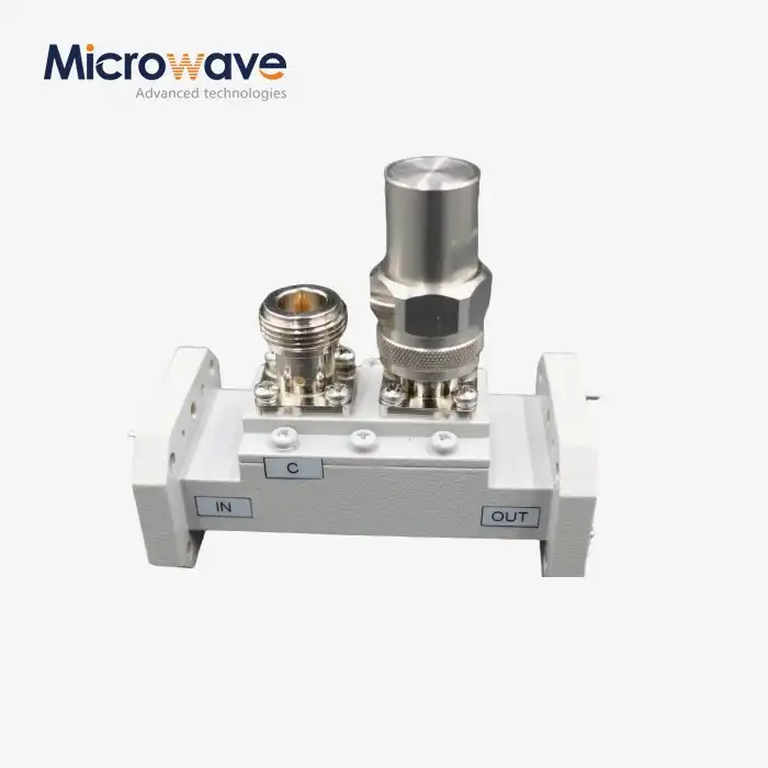 VIEW MOREDouble-Ridged Waveguide Loop Coupler
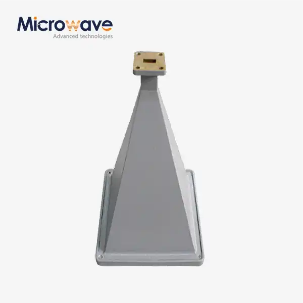 VIEW MOREPyramid Horn Lens Antenna
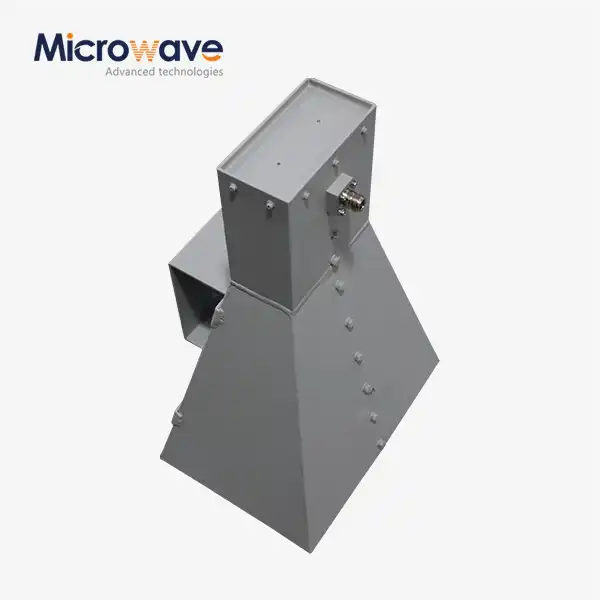 VIEW MOREWideband Double-ridged Horn Antenna
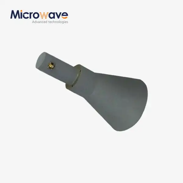 VIEW MORELadder Membrane Conical Dual circular Polarization Horn Antenna
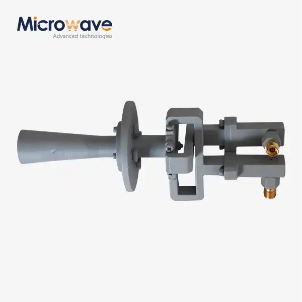 VIEW MOREConical Linear Polarization Horn Antenna
