Low Phase Noise Amps: Flicker Corner and Its Impact on SNR
Low phase noise amps are special RF parts that are made to keep the signal's spectral clarity while it's being amplified. In contrast to regular amplifiers that only care about gain or noise figure, these devices reduce the amount of added phase shift close to the carrier frequency. Signal-to-noise ratio (SNR) performance in mission-critical applications is directly controlled by the flicker corner frequency, which is where 1/f noise meets thermal noise. When procurement teams understand this relationship, they can choose amplifiers that keep signals intact in harsh environments like those found in satellite communications, radar systems, and precision measuring equipment.
Understanding Low Phase Noise Amplifiers and Flicker Corners
In current RF devices, success depends on how pure the spectrum is. When engineers test amplifiers for important tasks, they need to tell the difference between parts that are designed to reduce thermal noise and parts that are designed to deal with phase instability. This difference is very important in systems where even small timing mistakes can cause the signal to become severely damaged.
Core Characteristics of Phase Noise Amplifiers
Low phase noise amps are basically different from other RF parts because they are built with steadiness in time in mind. Traditional Low Noise Amplifiers (LNAs) try to reduce thermal noise that can be measured by noise figure. Phase noise-optimized devices, on the other hand, focus on carrier purity, which is measured in dBc/Hz at certain offset frequencies. For this design theory to work, you need to choose very specific semiconductors. For example, Heterojunction Bipolar Transistors in SiGe or GaAs processes can better reduce 1/f noise than regular CMOS implementations.
Electronic flicker noise is caused by charge carriers getting stuck in the crystal structures of semiconductors. Random trapping events make up most of the noise spectrum below the flicker corner. They cause low-frequency phase modulation that makes the carrier unstable. This corner frequency is pushed below 100 Hz by high-performance designs. This makes sure that the device works correctly across the important measurement window of 10 Hz to 10 MHz.
Defining the Flicker Corner Threshold
The flicker corner frequency shows the point where the noise power equals the thermal noise power. Below this point, phase instability gets worse as frequency goes down in a logarithmic way. Thermal noise keeps its spectrum density flat above it. This number is clearly shown in technical datasheets as a frequency value. Depending on the transistor technology and circuit layout, this value can be anywhere from a few tens of hertz to several kilohertz.
People who work in procurement should carefully read this standard. A device with a 500 Hz flicker corner has better close-in phase noise than one with a 5 kHz corner. This directly leads to better SNR in frequency generation and local oscillator uses. When systems use high-order modulation schemes like 1024-QAM, where constellation integrity depends on sub-degree phase accuracy, the difference can be seen.
Impact on Signal Integrity
Signal loss caused by poor phase noise performance shows up in different ways in different applications. In Doppler radar, jitter caused by the amplifier raises the noise level at close-in offsets. This makes it harder to see targets that are moving slowly because of ground clutter. When uplink frequency converters add too much phase modulation, bit error rates go up at satellite ground stations. There is timing jitter even in atomic clock references when flicker noise is added to the distribution chain by buffer amplifiers.
These real-life effects show why buyers in the defense, aircraft, and telecommunications industries put phase noise standards high on their list of requirements when choosing components. Because technical performance has a direct effect on operational capability, this parameter is not up for discussion and cannot be changed.
Low Phase Noise Amplifier Design Principles and Theory
Achieving outstanding phase noise performance needs advanced engineering in a number of areas. When device physics, circuit architecture, and thermal management come together, they make low-phase-noise amps that meet strict requirements for spectral purity. In this part, we'll look at the basic rules that make applications work.
Semiconductor Device Selection
The choice of transistor has a big impact on the phase noise floors that can be reached. Silicon Germanium HBTs have lower 1/f noise than silicon BJTs because they have better crystal quality and slower surface recombination speeds. Gallium arsenide processes are even better because they naturally have smaller defect rates, but they cost more to make. Buying choices are based on the trade-off between performance and cost. For example, aerospace uses need high-quality materials, while commercial systems have to weigh cost against meeting specific requirements.
Besides the choice of material, the shape of the transistor also affects its flicker noise input in low-phase-noise amps. When the emitter area gets bigger, the current density goes down, which makes charge trapping less effective. But as the device gets bigger, parasitic capacitance goes up, which limits how well it works at high frequencies. To get the best balance, designers use multi-finger layouts and careful bias point selection to run transistors in areas with little AM-to-PM conversion.
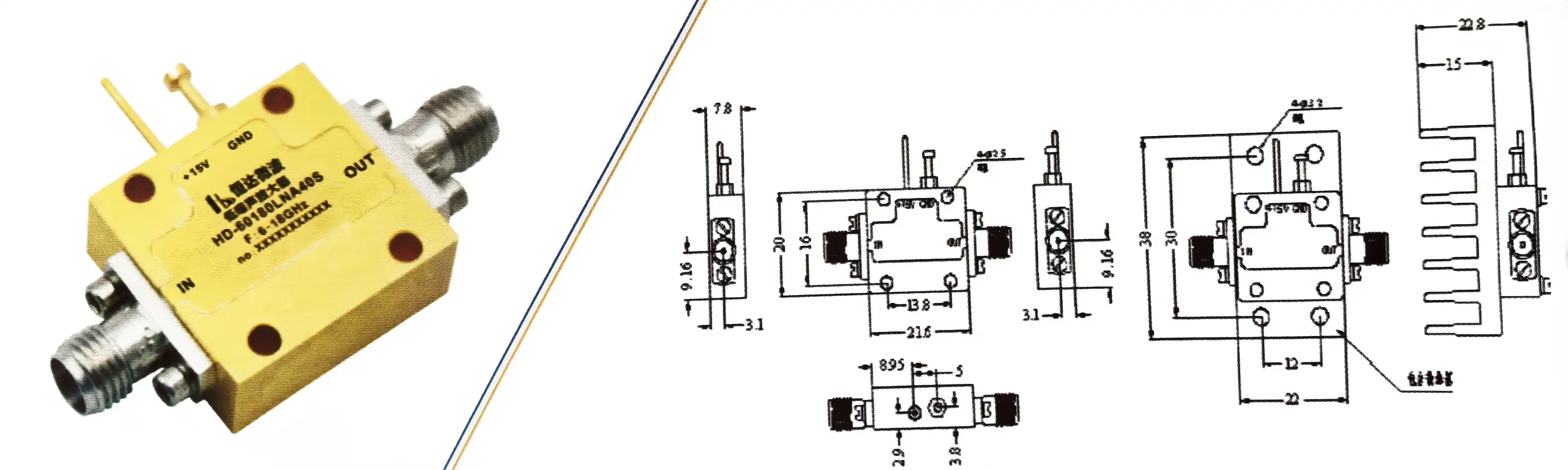
Circuit Topology Optimization
Cascaded amplifier stages spread the gain across several devices, so no single transistor can make the noise contribution too big. Differential designs naturally block common-mode disturbances, such as power source ripple, which changes bias conditions and causes unwanted phase modulation. When you trade raw gain for better uniformity, negative feedback designs lower the AM-to-PM conversion coefficients to less than 0.1 degrees per dB.
Stabilizing the temperature is also very important. Long-term stability is lost when phase drift happens because of changes in temperature, especially in outdoor installations where temperature changes a lot. When oven-controlled containers are used, junction temperatures are kept within ±0.1°C, but more power is used. Different methods use temperature-compensated biasing networks that change the operating points on the fly to counteract the effects of temperature.
Biasing and Power Supply Considerations
Ultra-low noise linear regulators provide DC power, and they pay close attention to output impedance at frequencies above 10 MHz. Power supply rejection ratio numbers show how well the amplifier blocks noise and ripple on the supply rails. If the rejection isn't good enough, the 60 Hz line frequency and its harmonics can change the bias of the amplifier, which makes isolated spikes in the phase noise spectrum.
The placement of bypass capacitors follows high-frequency layout rules, with values ranging from picofarads to microfarads placed right next to the input pins. This spread-out method makes low-impedance lines across the whole frequency range, which stops supply-induced variation from hurting phase performance.
Practical Impact of Flicker Corner on SNR in RF Systems
Theoretical requirements lead to differences in performance that can be measured in systems that are actually used. When procurement teams understand these connections, they can use measurable operational gains to defend the prices of parts.
SNR Degradation Mechanisms
Depending on how the system is built, phase noise can lower the signal-to-noise ratio in different ways. When direct conversion transmitters mix local oscillator signals that are tainted with flicker noise, they directly add this instability to the baseband signal. In digital modulation schemes, the phase modulation that results looks like constellation rotation, which raises the magnitude and rate of bit errors.
Frequency synthesisers with phase-locked loops are sensitive to amplifier phase noise in ways that depend on the loop bandwidth. The feedback action in the loop blocks contributions that are within its bandwidth, but noise at higher offsets gets through unaltered. This makes a design requirement that depends on frequency, with flicker corner placement directly affecting performance at close-in offsets where PLLs can fix the most.
Case Study Applications
Local oscillator signals are sent to dozens or even hundreds of antenna elements by phased array radar devices. Each distribution amplifier adds phase noise, and the total amount of noise increases as the number of parts increases. Using low phase noise amps with 1 kHz flicker corners instead of 100 Hz corners makes it much easier to find targets, especially for objects that move slowly and need Doppler resolution below 10 Hz.
Ground sites for satellite transmission show the same level of sensitivity. A normal X-band transfer frequency of 8 GHz is multiplied by frequencies that are lower in frequency. Phase noise gets bigger by 20 log₁₀(N), where N is the number that doubles. In the reference chain, amplifiers with low flicker corners keep the purity of the carrier during this multiplication process. This protects the link margin against thermal noise and allows for higher-order modulation.
Comparison with Standard Amplifiers
Standard RF amplifiers that are mainly made for gain and noise figure show flicker corners in the 1–10 kHz range. These devices work fine for receiver front ends where heat noise is the main problem, but they are not good for making signals. A direct study of the performance of normal and phase-optimized amplifiers in a 10 GHz frequency synthesiser shows phase noise differences of more than 20 dB at a 1 kHz offset.
Depending on the offset frequency bands that are important, this performance gap leads to SNR gains of 15 to 25 dB in real-world systems. This difference determines whether an application can work if it needs to pick up weak signals next to strong carriers, like radar clutter rejection or adjacent channel selectivity.
How to Choose the Best Low-Phase Noise Amplifier for Your System?
To choose the right component, you have to carefully compare the product's specs to the needs of the application. This organized method makes sure of the best performance while avoiding over-specification, which raises costs for no reason.
Critical Datasheet Parameters
The phase noise floor specs at different offset frequencies show how well the device works across the whole operational range. Check the readings at 100 Hz, 1 kHz, 10 kHz, and 100 kHz offsets. The best devices should show more than -165 dBc/Hz at 10 kHz. The flicker corner frequency should be shown clearly so that candidates can be directly compared.
Specifications for gain flatness and input/output VSWR show how well the device matches impedances across its working bandwidth. When VSWR is less than 1.5:1, reflections that make standing wave patterns are stopped. These patterns change the phase of the signal. The output third-order intercept point (OIP3) measures linearity; higher values mean less AM-to-PM conversion.
Supply Chain and Customization Considerations
For global B2B procurement, solid sourcing with supply lines that can be tracked is needed. Well-known companies keep their ISO 9001 certification and RoHS compliance up to date, which makes sure that the quality of each production lot is the same. There are big differences in lead times between catalog items and custom designs. Standard modules ship within weeks, but custom solutions take 8–12 weeks to create.
You can customize more than just the frequency range. You can also change the gain distribution, package styles, and environmental requirements. MIL-STD-883 screening is often required for defense applications. This adds cost but ensures reliability in harsh conditions. When catalog products don't meet the needs of an application, buyers should talk to manufacturers early on in the design process to look into custom solutions.
Cost-Performance Analysis
Price gaps between providers are caused by changes in technology and economies of scale. Commercial goods that are made in large quantities use automatic assembly and standard testing to get lower unit costs. Aerospace-grade parts go through a lot of screening and hermeticity tests, which is why they cost more because they are proven to be reliable.
At Advanced Microwave Technologies Co., Ltd. (ADM), we've been balancing these factors for over 20 years while working on tough projects involving low phase noise amps. In order to avoid both under-specification, which hurts performance, and over-specification, which raises costs needlessly, our engineering team helps buyers turn system-level requirements into component specifications.
Conclusion
The choice of low-phase-noise amps has a big effect on the SNR performance of the whole system in defense, aircraft, and telecommunications. The flicker corner frequency is a key parameter that determines how close-in phase noise behaves, with lower values indicating better signal integrity. When hiring people, procurement professionals need to carefully consider not only the details listed on the application forms but also the dependability of the supply chain, the ability to make changes, and the vendor's long-term support. New technologies promise that performance will keep getting better, but for now, mature processes offer the best mix between capability and business availability. Strategic relationships with experienced makers help buyers deal with these complicated technical issues so they can complete their missions on time and on budget.
FAQ
1. What distinguishes low-phase-noise amps from standard LNAs?
Standard LNAs improve the noise figure to keep the addition of thermal noise at the receiver inputs to a minimum. Low phase noise amps put temporal stability first, blocking flicker noise and AM-to-PM conversion, which are important for creating and sending signals. Because of this basic difference in design, each type can be used in different ways in RF systems.
2. How does flicker corner frequency affect radar performance?
Radar systems detect targets through Doppler shift analysis. Amplifier flicker noise elevates the close-in noise floor, masking slow-moving objects against clutter. Lower flicker corners keep the ability to detect targets moving slowly, which directly improves operational capability in surveillance applications.
3. Can custom amplifiers meet unique project specifications?
Companies like ADM make products that are specifically designed to meet the needs of different frequency bands, gain standards, and environmental conditions. Custom development usually takes between 8 and 12 weeks, and depending on how complicated it is, there are minimum order quantities. Early participation in the system design stages guarantees the best merging of components into the system.
4. What phase noise measurements should procurement teams request?
Ask for residual phase noise data at offset frequencies between 10 Hz and 10 MHz. The noise should be recorded using cross-correlation methods that separate source noise from amplifier effects. The necessary dataset for making smart buying choices also includes flicker corner frequency, AM-to-PM conversion coefficients, and temperature stability specs.
Partner with ADM for Superior Low-Phase-Noise Amplifier Solutions
Precision RF parts made by Advanced Microwave Technologies Co., Ltd. are designed for mission-critical applications that need very pure spectral signals. Our team has been making unique solutions for defense, aircraft, and satellite communication systems around the world for more than 20 years. Our modern measurement tools can test parts up to 110 GHz, and the parts we make have to meet strict ISO 9001:2015 and RoHS compliance standards.
Whether you're looking for catalogue items or custom designs, our tech support will help you make the right choice from the first review of your specifications to the delivery of your finished product. We know how hard it can be for procurement teams to make decisions because of all the technical details that need to be documented in great detail. Email craig@admicrowave.com to talk to one of our applications engineers about your project needs. We are a reliable provider of low phase noise amps, and our fast development, low prices, and reliable global logistics will help your projects stay on schedule and on budget.
References
1. Rohde, U.L., & Poddar, A.K. (2016). Low Phase Noise Oscillator Design: Fundamentals and Advanced Techniques. Microwave Journal Press.
2. Rubiola, E. (2009). Phase Noise and Frequency Stability in Oscillators. Cambridge University Press.
3. Everard, J.K.A. (2001). Fundamentals of RF Circuit Design with Low Noise Oscillators. John Wiley & Sons.
4. Pozar, D.M. (2012). Microwave Engineering, 4th Edition. John Wiley & Sons, Chapter 11: Active RF and Microwave Devices.
5. Maas, S.A. (2003). Nonlinear Microwave and RF Circuits, 2nd Edition. Artech House, Chapter 8: Noise in Nonlinear Systems.
6. Kroupa, V.F. (2003). Phase Lock Loops and Frequency Synthesis. John Wiley & Sons, Chapter 4: Phase Noise in RF Components.