Overheating and Arcing — Termination Waveguide Failure Modes
In high-power microwave and RF systems, the termination waveguide serves as a critical safety component designed to absorb excess electromagnetic energy and convert it into heat, preventing destructive signal reflections. When these devices experience overheating or arcing, the consequences extend beyond component failure—entire radar systems, satellite ground stations, and communication networks face catastrophic damage. Overheating occurs when thermal dissipation exceeds design capacity, while arcing results from voltage breakdown within the absorbing medium. Both failure modes compromise system integrity, damage expensive amplifiers, and halt mission-critical operations. Understanding these phenomena enables procurement engineers and technical teams to select robust components that ensure long-term reliability.
Understanding Termination Waveguides and Their Failure Modes
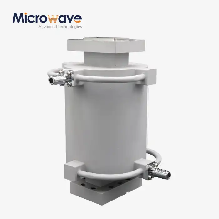
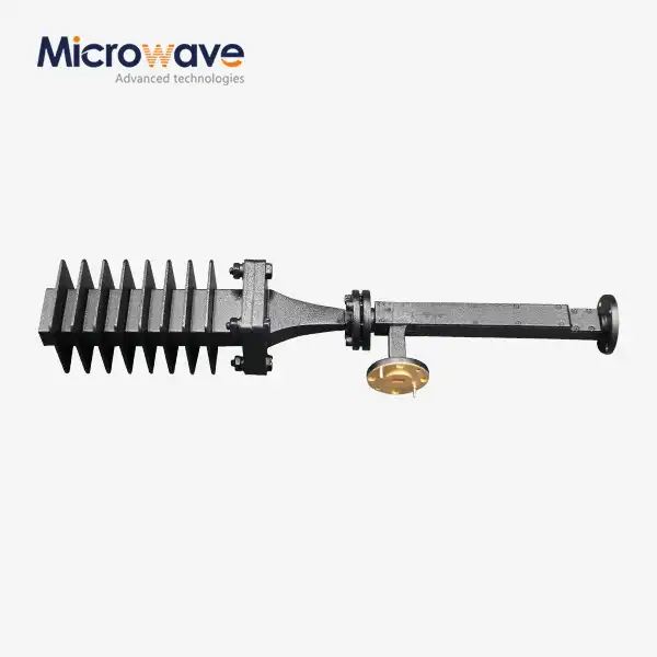
In microwave transmission systems, the endpoint is a termination waveguide, which is also known as a matched load or dummy load. Unlike regular waveguides, these special parts stop the path by matching the system's characteristic impedance, usually getting VSWR values below 1.15:1. This stops standing waves that could damage equipment upstream, like traveling wave tube amplifiers and solid-state power amplifiers.
Different design variations allow for a wide range of uses. Different polarization needs are met by E-plane and H-plane terminations, and broadband matching loads cover a wide frequency range, from L-band to Ka-band. In satellite communications and radar testing, the most common specs are industrial units that work between 1 GHz and 40 GHz.
Core Functions in Mission-Critical Systems
Termination waveguides keep sensitive source equipment safe by taking in power that would have gone back to magnetrons, klystrons, or semiconductor amplifiers if it weren't for them. During testing of radar systems, they allow non-radiating calibration, which lets engineers check the output of the emitter without any electromagnetic interference. In satellite ground stations, these devices protect high-power amplifiers when antenna misalignment or bad weather causes echoes that weren't predicted.
Recognizing Critical Failure Symptoms
Several visible signs of overheating include discoloration on the housing surface, warping of the mounting flanges, and measured VSWR degradation that goes beyond what is expected. Operators may smell strange things coming from dielectric materials that are breaking down, or they may see performance drift during continuous wave operations. Arcing has more dramatic signs, such as crackling sounds that can be heard, visible plasma discharge through gaps, and safety circuits that immediately cut power. Both problems need to be fixed right away because continuing to use them will damage them faster and put nearby system parts at risk.
When buying parts for defense contractors, telecommunications infrastructure, or research institutions where downtime costs more than $10,000 per hour, it's important for procurement professionals to understand these failure modes.
Causes of Overheating and Arcing in Termination Waveguides
Termination waveguides can fail early because of a number of interconnected factors. When engineering teams know these root causes, they can take preventative steps during both the purchase and installation stages.
Electrical Stress Beyond Design Limits
The most common reason for thermal failure is using more power than the device can handle. Localized hotspots form in the absorbing material when incident power goes over the continuous wave rating of the termination or when peak pulse power goes over voltage breakdown thresholds. When 150 watts are applied to a termination that is rated for 100 watts CW, it breaks down faster, and the temperature inside rises above what is safe for use. Signal reflections from loads that aren't properly matched form standing wave patterns that focus energy at certain places, making thermal stress even higher.
Material Properties and Design Constraints
The composition of the absorbing element directly affects how likely it is to fail. Carbon-impregnated wedges are cheaper than silicon carbide ceramics used in high-end units, but they don't conduct heat as well in termination waveguides. During high-duty-cycle operations, temperature spikes happen because of design flaws like not enough surface area for convective cooling or not enough mass for thermal capacity. Differences in the uniformity of the dielectric constant during manufacturing can lead to impedance mismatches that heat up specific areas instead of absorbing energy evenly.
Installation Errors and Environmental Factors
When the torque on the flange isn't right, air holes form that mess up the spread of electromagnetic fields and make it harder for heat to move to the mounting surfaces. When installation isn't done correctly, reflection factors are introduced that stop the termination from matching. Environmental factors make these problems worse. High temperatures lower the available thermal headroom, humidity changes the dielectric qualities, and mechanical vibrations in marine or flying uses loosen connections over time. When dirt builds up on the cooling fins or inside the waveguide hole, it makes it harder for heat to escape, which raises the working temperature close to the point where it breaks.
Because of these things, similar termination models have very different service lives based on the conditions of use and the quality of the installation. When writing specs for purchases, it's important to think about the worst possible environmental situations and include enough safety gaps.
Principles and Best Practices to Prevent Overheating and Arcing
To keep big problems from happening, you need to pay close attention to design choices, installation instructions, and operating tracking. Organizations that implement comprehensive practices report termination waveguide lifespans of more than fifteen years in demanding applications.
Choosing parts that meet the right requirements is the first step in making something reliable. Power ratings should include safety factors of at least 1.5x for applications that run all the time and 2x for pulsed radar systems where peak power is much higher than average values. It's important to choose the right materials. Silicon carbide absorbers can handle higher temperatures than regular carbon composites, and copper housings are better at transferring heat than aluminum ones, but they are heavier.
Installation Procedures That Ensure Longevity
Using the right mounting method has a direct effect on thermal performance. To make sure that the gasket compresses evenly and there is good thermal contact, flange connections need calibrated torque wrenches that use manufacturer-specified values, which are usually 20 to 40 inch-pounds for standard WR-90 waveguide sizes. To avoid angular mismatches that cause reflections, alignment pins must fully engage before being tightened. The thermal interface materials between the termination housing and heat sink make it easier for heat to flow and lower the resistance of the contacts in high-power situations. Vertical mounting positions help natural airflow, while horizontal placements might need forced air cooling to keep temperatures at a good level.
Proactive Monitoring and Maintenance Strategies
Protocols for regular inspections find signs of wear and tear before they cause a catastrophic failure. Thermal imaging scans find hot spots that mean there is damage inside or a problem with cooling. Every year, network analyzers are used to check the VSWR and make sure that the return loss stays within the acceptable range. If the VSWR goes from 1.10:1 to 1.25:1, it means that the absorber is wearing out and needs to be replaced. Visual inspections look for damage to the cooling fins, discolored housing, and deformed flanges. Keeping track of operating hours and power levels lets you replace parts before they break down and stop operations.
These methods are in line with the quality control systems that ISO 9001 standards call for, and help meet the needs of aerospace and defense buyers for traceability. When compared to reactive maintenance methods, these guidelines help organizations cut down on unplanned downtime by over 70%.
Comparing Termination Waveguides to Alternative Components
Understanding the differences between termination waveguides and related parts makes it easier to understand how they fail and when they should be used.
Standard waveguides move electromagnetic energy with little loss, but termination waveguides are designed to lose energy on purpose. Because of this basic difference, the thermal loads are very different. For example, a normal WR-90 waveguide working at 10 GHz might lose less than one watt per meter, but a termination takes in all the power and turns it into heat. Because of this, terminations need strong temperature control that transmission waveguides don't have.
Attenuators lower the level of the signal but still let some of it pass through, while terminations reflect almost nothing. This difference has an effect on how things fail. Attenuators usually break because the value drifts slowly over time, while terminations break suddenly and catastrophically when thermal limits are exceeded. Similar tasks can be done by dummy loads in a coaxial form factor, but they can't handle the high power densities that are common in waveguide systems that work above 5 GHz.
Evaluating Supplier Quality and Reliability
Material quality and manufacturing accuracy vary a lot from one supplier to the next. Precision casting is used by well-known companies like Times Microwave Systems to make sure that the housing is regular, and computer-controlled dielectric machining is used to make sure that the absorber shape of the termination waveguide is always the same. Some of the middle-tier suppliers, like Pasternack, have catalogs with standard products that can be used in a wide range of industrial settings. However, these products can't be changed much to meet specific needs. Premium European makers, like Huber+Suhner, offer more test paperwork and tighter tolerance control, but their products cost 30–50% more than similar Asian-made options.
Advanced Microwave Technologies Co., Ltd. fills this need by combining manufacturing methods that are ISO 9001:2015 certified with the ability to make changes that aren't usually possible from catalog suppliers. Our factories use precise CNC machining and special absorber mixes that have been tested in temperatures ranging from -40°C to +85°C to make sure they work the same way in all conditions. With measurement powers up to 110 GHz and more than 20 years of production experience, we offer the same level of reliability as the best European providers while keeping our prices low.
When making a purchase decision, the total cost of ownership should be taken into account. This includes things like failure rates, warranty coverage, and how quickly technical support can help. Terminations cost less than 2% of the average cost of a system, but they keep parts worth tens of thousands of dollars from breaking down.
Procuring Reliable Termination Waveguides: What Buyers Should Know?
To strategically buy termination waveguides, you need to make sure that the technical specs match the business needs while also keeping an eye on the supply chain.
The frequency range coverage is one of the most important selection criteria. You should list the full operating bandwidth, including guard bands, not just the center frequency. Power ratings must take into account both the average power that is used continuously and the peak power that is pulsed. There must be a clear separation between CW and pulsed specifications. Environmental factors, such as the operating temperature range, how height affects cooling, and the amount of shock and vibration that is acceptable, make sure that the product is suitable for the places where it will be installed.
Leveraging Customization and Volume Benefits
Standard catalogue terminations work well for many uses, but custom solutions get the best performance and value for money. Customized flange types work with older equipment connections, unique cooling setups make the most of limited space, and custom absorber formulations increase the amount of power that can be handled. Costs can be cut by a lot when you buy in bulk. Orders of ten or more units usually get savings of fifteen to twenty-five percent. Also, yearly contracts with forecast promises can cut unit costs by thirty to forty percent compared to spot purchases.
Selecting Suppliers With Comprehensive Support
Certifications are objective proof of the ability to make something. ISO 9001:2015 confirms quality management systems, and RoHS compliance makes sure that environmental rules are followed in the European and North American markets. It's very important for suppliers to offer good technical support. Being able to talk to RF experts who know how to integrate systems can help avoid making mistakes that cost a lot of money. The warranty should cover problems with the way the product was made for at least two years, and there should be clear steps for getting a repair or return authorized.
Through our world transportation network, Advanced Microwave Technologies Co., Ltd. can help you with all of your purchasing needs. We keep common waveguide sizes in stock and can deliver them to North American addresses in two weeks. Custom designs, on the other hand, usually ship six weeks after the order is confirmed. Our technical team helps with planning system integration, analyzing power budgets, and making sure that stated parts meet real operating needs. For important applications, prototyping services lower the risk of buying things by letting you test their performance before committing to large quantities.
Negotiation strategies should focus on building partnerships instead of just doing business. Suppliers who know your application roadmap can suggest better technologies for termination waveguide and deal with problems before they happen. Multi-year contracts with price-hiking clauses and volume commitments protect against rising prices for goods and make sure there is a steady supply.
Conclusion
Overheating and arcing in termination waveguides are caused by too much power, limitations in the material, mistakes in installation, and environmental stresses that make it hard to control temperature. To avoid these problems, you need to carefully choose the parts you use and make sure there are enough safety gaps. You also need to carefully install them by following the torque and alignment instructions, and you should keep an eye on things by using thermal imaging and VSWR tests. Understanding the differences between termination waveguides and other parts helps with the right application. Evaluating the quality, licenses, and support capabilities of suppliers ensures that choices about buying balance cost with dependability. By following these thorough steps, companies can protect their expensive RF source equipment, make it last longer, and avoid downtime. This is useful for radar, satellite communication, and precise measurement.
FAQ
1. What causes most waveguide termination failures?
About 60% of failures are caused by thermal stress from using more power than the device is allowed for, and another 25% are caused by a bad fit that leads to reflection and poor thermal contact. Most of the remaining failures are caused by environmental factors like humidity getting in and mechanical vibration. Most early failures can be avoided by choosing parts with enough power margins and making sure they are installed correctly.
2. How often should terminations be inspected?
For high-power, continuous-duty uses, thermal imaging surveys should be done every three months, and VSWR verification readings should be taken once a year. Visual checks every six months and performance tests every two years are good for moderate-power systems. Pulsed radar systems should be checked every 5,000 hours of use or once a year, whichever comes first. Predictive replacement methods work better with inspection records that are written down.
3. Can damaged terminations be repaired?
When terminations show arcing damage or VSWR decline above 1.30:1, they usually need to be replaced instead of fixed. Thermal shock and voltage breakdown change the structure of the absorbing element in a way that can't be undone. Minor damage to the housing, like discoloration for looks, doesn't affect performance and can be used again, but damage to the absorber inside the unit needs to be replaced completely to protect the system.
Partner With ADM for Dependable Waveguide Termination Solutions
Advanced Microwave Technologies Co., Ltd. makes termination waveguide solutions that are designed to keep your most demanding applications safe from burning and arcing. Our ISO 9001:2015-certified manufacturing processes and thorough testing in our 24-meter microwave darkroom make sure that every unit meets strict performance standards before it is shipped. Our technical team is here to help you with all of your selection and integration needs, whether you need regular catalogue items or special designs for specific frequency bands and power levels. We are an experienced termination waveguide manufacturer that works with the defence, aerospace, and telecommunications industries around the world. We offer low prices, quick prototypes, and reliable shipping all over the world. Get in touch with craig@admicrowave.com right away to talk about your needs and get a detailed quote that comes with full technical support and a warranty.
References
1. Carter, R.G. "Microwave and RF Vacuum Electronic Power Sources." Cambridge University Press, 2018.
2. Pozar, David M. "Microwave Engineering, 4th Edition." John Wiley & Sons, 2011.
3. Saad, Theodore S. "Microwave Engineers' Handbook, Volume 2: Passive and Active Components." Artech House, 2019.
4. IEEE Standard 1128-1998. "IEEE Recommended Practice for RF Absorber Evaluation in the Range of 30 MHz to 5 GHz."
5. Bhat, B. and Koul, S.K. "Analysis, Design and Applications of Fin Lines." Artech House Microwave Library, 1987.
6. Silver, Samuel. "Microwave Antenna Theory and Design." MIT Radiation Laboratory Series, Boston Technical Publishers, 1964.