




What Causes VSWR Spikes in a Waveguide Cable Assembly?
VSWR spikes in a waveguide cable assembly are usually caused by a change in impedance that sends some of the signal back to the source. Most of the time, triggers are dirty or broken flanges, joints that aren't lined up correctly, waveguide-to-coax transitions that are too tight, tight bends that deform the flexible core, and resonances inside the assembly. Temperature, vibration, and high power are some of the things that can change these effects. Not having the right filter, load, or calibration setup can also look like a fault. First, look at how the test looks. After that, look at each one. Lastly, take the assembly apart using a part that you know is good. We can use this guide to find and fix each cause. It is important to have a spike because reflected power lowers the delivered power, strains amplifiers, and messes up measurements. To make it easier for everyone to understand, we talk about the causes, testing, and choices all in one place.
What Is VSWR in a Waveguide Cable Assembly?
How VSWR Relates to Return Loss and Insertion Loss
Voltage Standing Wave Ratio (VSWR) measures how much of a signal bounces back when the impedances don't match up. The reflection coefficient can be found by Γ = (VSWR - 1) / (VSWR + 1). The reflection coefficient is about 0.11, the return loss is about 19 dB, and about 1.2% of the power is lost when the VSWR is 1.25:1. At 2:1, the return loss drops to about 9.5 dB, and about 11% of the power flows back. Another way to measure is to add up the loss. It shows how much power the part loses as it goes along. Since a part can have both low VSWR and low insertion loss, we look at them together.
Spike Versus Consistently High VSWR
There’s a distinction between a spike and a constant high reading. Most of the time, a high VSWR throughout the full band suggests the waveguide is too narrow, the termination is damaged, or the calibration is incorrect. If something rises really rapidly, the pace is called a spike. A tiny recurring peak is typically a symptom of a resonance or a local breach, such as a gap at a joint. A spike that appears and disappears might frequently be due to noise, temperature fluctuations, movement, or a loose connection. If we write down the frequency, height, breadth, and how many times each spike occurs, it might help us figure out where to start searching.
Matching Waveguide Size and Frequency Band
Each size of the rectangular waveguide may be used for a variety of frequencies. The WR-90 operates in the X-band (8.2 to 12.4 GHz), the WR-75 in the X-band (10 to 15 GHz), and the WR-28 in the Ku-band (26.5 to 40 GHz). A waveguide won't go below a given frequency. The WR-90 stops operating at about 6.56 GHz. Mismatches occur when you mix sizes or run components outside their recommended range. This may give the impression that there is an issue with the waveguide cable assembly. Before any troubleshooting, we always examine the name, operating band, and kind of flange (CPR, UG, UBR, etc.).
The Most Common Causes of VSWR Spikes
Flange, Connector, and Transition Problems
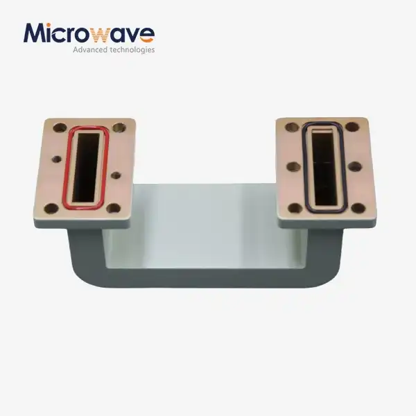
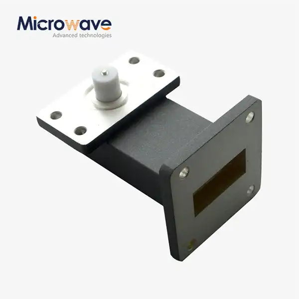
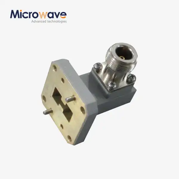
The road connects to other trails at its highest spikes. A little gap bounces energy about. It might be dirt, a scratched flange face, or bolts not fully tightened. If the flanges are out of line, the impedance changes. This is because they produce a step in the wall of the waveguide. Even waveguide-to-coax transitions with SMA connections need careful planning, alignment, and calibration. They add another interface that has to be utilised. This may occur if the plating is not excellent or if the junction of the part is not straight. These flaws will thus likely appear as persistent acute peaks. We inspect and clean all the probable surfaces before we condemn the part itself.
Bending, Twisting, and Internal Deformation
A flexible waveguide may be bent and twisted because its core is interlocking or convoluted. The core may change form if bent too little, twisted, or if the weight is left hanging unsupported. The cross-section determines the impedance, and even minor damage may modify it. This normally produces a spike that travels with the cable. Also, if you push, pull, or bend it more than the specified number of times, it will be ruined. There are limitations for rolling and static bending on each data sheet. We care a lot about these values, since core damage might endure a long time.
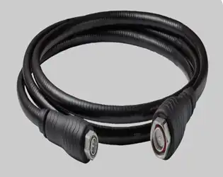
Resonance, Environment, and System-Level Mismatches
The inside of an assembly may include tiny resonant cavities due to its design and size that give narrow peaks at certain frequencies. If the temperature changes, you might get vibration shocks or strong power. These may change the alignment or contact pressure. Dirt or a sharp edge nearby might potentially cause arcing. Similar issues might develop if the antenna, filter, load, or test fixture is not matched to the assembly. Loose old calibration kits and adapters may provide false values. We look at the entire RF chain before we start pointing fingers. These effects often mix in orbit, on radar, on satellites, and out. So a single test at room temperature may miss an increase during use.
How to Diagnose a VSWR Spike Step by Step
Start With the Test Setup
We verify the size before we touch the hardware. We verify the VNA calibration technique, the calibration plane, the adapters being utilised, and the torque on each joint. We also evaluate the stability and cleanliness of the test ports. If the calibration is inaccurate, there might be a large inaccuracy throughout the band that will seem like a damaged portion. Then we record how many spikes there are, how tall they are, how broad they are, and how frequently they occur. You can see whether the spike is stable or not by sweeping it two or three times. These remarks are also clearer so that engineers at a supplier may find out what is wrong more quickly.
Inspect, Substitute, and Locate the Reflection
Next, we inspect the flanges, gaskets, flexible parts, strain relief, and hardware for dirt, dents, and other indications of wear. If we cannot see anything, we load or switch in a known-good waveguide cable assembly. The first portion is what got rid of the spike. If it's still there, danger farther down the line. If the analyser is capable, time-domain or distance-to-fault analysis may translate the measurement to a path location. That informs us whether the reflection is from the part's center, distant, or near the flange. So we test it again, but this time with real temperature, real vibration, real location, real power.
Match Spike Patterns to Root Causes
The solution is provided in a manner that gives clues. If the spike is modest and constant, it might represent a resonance, a transition mismatch, or a local discontinuity. If the band does come up, then there might be many reasons for this. The waveguide could be the incorrect size, there could be serious damage, the termination could be poor; or the calibration could be inaccurate. If the spike moves with the cable, the connections are loose, or the bend radius is too narrow. A spike that only happens at a high power or temperature might signify contamination, arcing, or thermal movement. There is no issue. Most of the time, a new flange junction spikes because the bolts are not tightened sufficiently. If, when the system is all assembled, the spike is still there, check the load, antenna, or filter. Each guess is always verified by creating a new guess and reviewing the previous guess.
Flexible vs. Rigid Waveguide Assemblies and Coaxial Cable
Flexible Waveguide Assemblies
Flexible parts work well with antenna feeds, moving platforms, radar gear, test systems, and small areas where the wiring needs to be changed. Slips and vibrations that would stress rigid pipes are taken in by them. What makes them stable in terms of VSWR are the minimum bend radius, twist control, strain relief, and the rated number of flex cycles. It's called "twistable" if it can bend and rotate around its axis. Types that can only bend can only bend in the E and H planes. Because the core can move, you need to be extra careful when working with flexible assemblies. It's important for phased arrays and VNA measurements that the phase stays stable when the array is bent, so we suggest that you ask for phase data when you need it.
Rigid and Hybrid Assemblies
Rigid assemblies don't change shape, so they have good dimensional stability and low-loss performance all the time. Fixed links, high-power systems, lab equipment, and spacecraft are some of the things they work with. Getting aligned costs money. For rigid runs, the flanges have to be put exactly where they need to be. If they aren't, the joints are put under stress or a step. Custom transitions, rigid sections, flexible sections, and elbows are all parts of hybrid assemblies. These are useful when a standard part can't finish the job or meet the VSWR needs. In the case of an antenna port that can be moved, a short flexible section can handle the movement while the signal is sent along the rest of the path by rigid runs.
Waveguide Cable Assembly vs. Coaxial Cable
Look at them on the whole app, not just a part of it. Most of the time, coaxial cable has a lot more insertion loss and can't handle as much power as waveguide at microwave frequencies above 18 GHz. There is still no better way to route and set up coaxial cable at low and medium frequencies. Every time the waveguide changes to coax, there is an extra interface. If the transition isn't well planned, aligned, or calibrated, reflections can happen. Things to think about are space, routing, environment, frequency, power, VSWR, insertion loss, and the cost over the lifecycle. In the next step, check the whole assembly, including the changes, across all the operations.
How to Prevent Spikes and Choose a Stable Waveguide Cable Assembly
Installation and Handling Habits
You don’t need a lot of spikes. Align the flange and connection and clean the surfaces before joining. Then, utilise hardware and gaskets that are compatible. Tighten the bolts in the sequence shown until the specified torque value is obtained. That the flexible waveguide is free of any severe bends, twists, compressions, or unsupported weight and that it remains above the prescribed bend radius. Make a strategy for the environment, too. The part may be damaged by temperature, humidity, salt spray, vibration, stress, corrosion, shipment, and storage. During the first inspection, all the measurements, quality of work, connections, and materials should be examined. Sweep frequency, VSWR, and insertion loss should be evaluated for acceptability, and the limits and calibration conditions set down.
Specifications to Put in Your Request
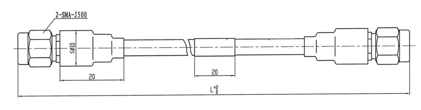
Both sides are safe after reading the full article. When specifying a waveguide cable assembly, you should also note the waveguide name, the frequency range, power level, maximum VSWR, insertion loss, length, bend radius, flex life, flange or connection type, materials, plating, sealing, and outside requirements. Most of the WR-90 and WR-75 configurations will work with standard parts. For unusual lengths, unique transitions, severe VSWR limitations, high power, or tight routing, custom assemblies are the best way to proceed. Lastly, evaluate how the supplier assists with design, test reports, quality processes, lead time, export paperwork, packing, warranty, and follow-up after the sale. So make sure that the plots you obtain cover your whole operational band. There is more to be learned from measured sweep data than from a claim.
What ADM Offers for Your Project
ADM has been developing RoHS-compliant goods for over 20 years and understands a lot about microwaves. If you have a VSWR problem, these services are helpful:
- Design support: Our experts will analyse your frequency band, flange type, routing and VSWR limit and provide recommendations for a conventional or bespoke waveguide cable assembly. This early evaluation detects discrepancies in size, interface and bend restrictions before the part reaches your test bench, so your team spends less time on rework and retesting.
- Prototyping and fast turnaround: we construct prototypes for test and evaluation before full-scale manufacturing. You may evaluate VSWR and insertion loss on an actual sample, compare the findings with your limitations, and adapt the design early. We handle efficient production and delivery procedures to keep projects on time and minimise waiting between design reviews.
- Technical assistance and measurement: Our professionals will help you with installation and troubleshooting. If a spike develops, we may pull up your sweep data, examine the causes of the surge, and recommend the next test. We have testing equipment in our facilities up to 110 GHz so we can verify VSWR throughout the common waveguide bands.
These services reduce the time to acquire a real repair for a VSWR issue.
Conclusion
When there are changes in impedance in a waveguide cable assembly, VSWR spikes happen. The shape of the spike helps figure out what caused it. A lot of the time, flanges, transitions, resonances, or damage in one area cause narrow peaks to show up over and over again. If there are broad rises, it could mean that the size is off, the termination is bad, or the calibration is off. The cable might bend or twist more than it should if the spikes move with it. Check the calibration, clean the interfaces, replace it with a known-good part, and if you can, use distance-to-fault analysis. This is the only way to fix it reliably every time. If the waveguide sizes are matched, the installation is done carefully, and data is sent over the whole operating band, there shouldn't be many problems. Flex, rigid, and hybrid designs all have different routing needs. When buyers first say what they want, like VSWR, insertion loss, bend radius, and environment, they get more accurate results than when buyers only look at price.
FAQ
Q1: What VSWR is acceptable for a waveguide cable assembly?
It depends on the frequency, the amount of power, and the amount of loss you can handle. Set a minimum return loss or maximum VSWR for the whole operating band before you ask for quotes. There are a lot of high-performance assemblies that aim for 1.25:1 or less, but your application will tell you the real limit.
Q2: Why does VSWR spike only when the cable moves?
Most of the time, movement means that the bend radius is too small, the flexible core is broken, or a joint is loose. Check the part's strain relief and put it through a few different tests. Then, get an assembly that you know works and compare it to the ones you made. The cable is broken if the spike goes with it.
Q3: Does low insertion loss mean low VSWR?
VSWR tells you how much power the part returns, while insertion loss tells you how much power it loses. A part can still show a spike even if it hasn't lost much. Also, WR-90 and WR-75 assemblies are not compatible with each other as they have different frequency ranges and sizes.
Request a Waveguide Cable Assembly Quotation from ADM
Email ADM at craig@admicrowave.com with the frequency, waveguide size, VSWR target, length, flange type, and number of items you need. As a waveguide cable assembly supplier, we can look at your needs and offer either a standard or a custom solution. We also offer OEM services, prototyping, technical support, and shipping all over the world.
References
1. Microwave Engineering, David M. Pozar, Wiley, 2011.
2. Foundations for Microwave Engineering, Robert E. Collin, Wiley-IEEE Press, 2001.
3. Fundamentals of Vector Network Analysis, Michael Hiebel, Rohde & Schwarz, 2008.
4. Understanding the Fundamental Principles of Vector Network Analysis (Application Note 1287-1), Hewlett-Packard, 1997.
5. IEC 60153-2: Hollow Metallic Waveguides, Part 2: Relevant Specifications for Ordinary Rectangular Waveguides, International Electrotechnical Commission, 2016.
6. Microwave Engineering: Passive Circuits, Peter A. Rizzi, Prentice Hall, 1988.