





High Power Coaxial Switch Specs That Make or Break Your RF System
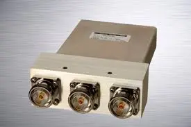
Your RF system will work or not depend on how well its frequency range, continuous wave and peak power, insertion loss, isolation, VSWR, switching mode, and connector type all work together. RF energy is sent between paths by a high power coaxial switch. This means that a weak rating can cause heat, reflections, or signal leakage. Buyers often only look at the power number and don't pay attention to the interface, the derating curve, or the hot-switching limit. We explain each parameter in simple terms in this guide, and we also show you how to check the requirements before you place an order.
How a High Power Coaxial Switch Works
Controlled Impedance and Internal Parts
When an RF path is made or broken, a high power coaxial switch keeps the transmission line at its design impedance, which is usually 50 ohms. The signal is sent inside by RF contacts and short transmission line sections. The contacts are moved by an actuator, which is controlled by a control circuit. The result is shown by a position indicator. Any change in the internal geometry can lead to a reflection, so the dimensions inside are just as important as the connectors on the outside. Reflections cause heat and warping. Because of this, a switch in test equipment, radar, broadcast, satellite, or industrial service needs to be able to keep its impedance across the whole operating band, not just at one frequency.
Normally Open, Normally Closed, and Latching Designs
What the switch does when the power goes out depends on how it is set up. When the coil loses power, a normally open or normally closed model goes back to its default path. This keeps the transmitter chain safe from an unknown state. When the power goes out, a latching model stays in its last position without holding current. This keeps the coil cool and the path in place. Before you compare models, you should figure out what position the system needs after a fault. Position indicators are important here because before the transmitter turns on, the controller should make sure that the actual path matches the command.
Hot Switching and Cold Switching
When there is no RF energy present in a high power coaxial switch, the contacts move. This is called "cold switching." When you hot switch, the RF power stays on while you move. While switching from cold to hot, arcing and contact pitting can happen. This means that a power rating written for cold switching can drop sharply when RF is live. When you need high isolation and high power routing, electromechanical designs are often the best choice. Solid-state switches, on the other hand, are best for fast response and high cycle rates. Both ratings can be found on the datasheet. If your sequence control can turn off the transmitter before the switch moves, you can keep the contacts safe and often get away with a simpler part.
The Core High Power Coaxial Switch Specifications
Frequency Range, Power Handling, and Derating
Power ratings change based on temperature, duty cycle, frequency, and pulse width. In books about microwave engineering, it is written that as frequency goes up, so do conductor resistance and heat. It's possible for a part to meet one rating but not the other. This is because continuous wave (CW) power is limited by heat and peak power is limited by voltage breakdown. Don't settle for a single number; ask for the derating curve instead. Read it at the top of your band. A score given at the bottom of the band might not be valid at the top, and a warm cabinet lowers the limit even more.
Insertion Loss, Isolation, VSWR, and Return Loss
These four pictures show the quality of the signal. The power that is lost in the closed path is called insertion loss. It is turned into heat: 0.1 dB at 1 kW turns about 23 W into heat inside the switch. Leakage into the open path is what isolation means. At 60 dB, 1 kW only leaks 1 mW, but a receiver that is very sensitive might need more room. That's what VSWR and return loss are for. A VSWR of 1.2:1 shows about 0.8% of the power that hits it, while a VSWR of 2:1 shows about 11%. It's important to go over all four with the whole band because they work together.
Switching Speed, Contact Bounce, and Switching Life
There are three parts to switching speed: command response, mechanical settling with contact bounce, and RF settling. A lot of datasheets only list the first one. For a short time, bounce can block the RF path, so radar and test sequences should use the settled time. Cycles are used to measure switching life, and for electromechanical models, the number of cycles is often in the millions when switching is cold. A test bench that changes positions every minute goes through about 525,600 cycles a year, which means that a rating of one million cycles doesn't last more than two years. Find out if the rating is based on cold switching, and what the lowest contact resistance level is that means the end of the life.
Which Specification Deserves the Highest Priority?
Priority comes after the application. Stable impedance and good connectors are needed for low-loss systems. For receiver protection to work, there needs to be a lot of isolation, shielding, and consistent contact positioning. For fast systems to work, command response and RF settling must be kept separate. High-power transmitters need CW and pulsed ratings that have been checked, as well as thermal data and limits for hot-switching. The same care should be given to impedance. For most RF and microwave work, use 50-ohm designs. Only use 75-ohm designs for systems that were built to work with them, like some broadcast video paths. Do not switch them without checking at the system level, as the difference can lead to reflections.
Types, Configurations, and Technology Choices
SPDT, SPnT, Transfer, and DPDT Configurations
One of two paths can be chosen by an SPDT switch, like a main transmitter and a backup transmitter. One port on an SPnT switch can connect to more than one output, making it useful for antenna selection, automated test equipment, and routing over multiple bands. With a single command, a transfer or DPDT design can switch two transmitters and two loads at the same time. Figure out your signal map and pick the simplest configuration that works. As more paths are added, internal line length, loss, and possible leakage all go up. This is why a bigger switch should only be used when the system really needs it.
Connector Choices: SMA, N-Type, 7/16 DIN, TNC, and BNC
Most of the time, the connector sets the limit. SMA works well with microwave frequencies and small layouts, but it doesn't carry as much power as bigger interfaces. N-type can handle more power and is commonly found in communications and broadcasting gear. The threaded version of BNC is called TNC, and it works at higher frequencies. BNC, on the other hand, works at lower frequencies and with less power. In wireless infrastructure, 7/16 DIN is used for high power and low passive intermodulation. Advanced Microwave Technologies Co., Ltd. (ADM) sells waveguide assemblies, coaxial assemblies, and cable assemblies. This means that adapters and cables that connect to the switch interface can be looked at together.
Electromechanical vs. Solid-State Switches
High isolation, low off-state leakage, low insertion loss, and strong power handling are all things that electromechanical models usually have. They have wear and tear on the parts and switch more slowly. When switching between states, solid-state designs do it quickly, quietly, in small packages, and with a lot of cycles. It's important to keep an eye on their heat, linearity, biasing, and power limits. When it comes to transmitter routing and receiver protection, electromechanical parts are often better, but solid-state parts may be better for fast automated tests. Make sure you know what you need for hot-switching and how long you expect the technology to last before you choose it.
High Power vs. Standard Coaxial Switches
A high power coaxial switch has better insulation, stronger contacts, a better heat path, and a stronger build. It is also often sealed against the environment. It meets the requirements for higher average or peak power. You can still use a standard switch for low-power work in the lab, for monitoring, or on the receiver side, but only after you check the real system conditions. Take a look at the total cost of ownership. One broken switch in a radar or broadcast chain means downtime, a field visit, and a replacement. This means that a higher purchase price can save money in the long run.
Selection, Procurement, and Applications
A Step-by-Step Selection Process
Do not start with the catalogue but with the system. Log the frequency of operation, type of signal, power profile, duty cycle, switching status, and environment. Then, specify the minimum values of VSWR, switching speed, insertion loss, impedance, and power handling. Then choose the connectors, mounting, control interface and circuit configuration. Finally, request derating curves, test reports, life cycle data, certifications, warranty information, lead times, and after-sales assistance from the supplier. Most late-stage redesigns may be avoided by reviewing them before they get to production.
RFQ and Customization Checklist
I believe every RFQ should have these elements in it.
- Electrical requirements: Frequency range, impedance, average and peak power, duty cycle, circuit layout, and switching speed. Also include whether the switching is with RF on, and what load VSWR you anticipate, since those facts modify which designs qualify.
- Mechanical and control requirements. List connection types, mounting dimensions, control voltage or remote protocol, position feedback, interlocks, sealing and environmental conditions. These parameters tell us whether a regular switch would suffice or if they require a specialised housing or control interface.
- Commercial requirements: Annual volume, delivery dates, labelling, packaging, compliance documentation and relevant test results. Clear business terms allow a supplier to arrange prototypes, bulk manufacturing and export documentation without recurring questioning.
With this knowledge, an engineer may propose a conventional model or begin planning a unique design. ADM provides OEM services, prototypes, and technical support.
Application Examples
Priorities change depending on the use. Repetition, low loss, high isolation, remote control, and cycle life are all important for microwave test systems. Defense and radar equipment needs to be able to handle high power, last a long time, work without problems, and have tests that can be tracked. Low mass, thermal stability, vibration resistance, and qualification evidence are some of the most important things in satellite and aerospace hardware. There is a known risk of multipaction in vacuum that is taken care of by space standards. Broadcast and communication sites put a lot of emphasis on CW power, impedance compatibility, monitoring from a distance, and the durability of connectors. For industrial RF heating to work, it needs to be able to control temperature, stop arcs, give service access, and be tested under real duty cycles.
Mistakes and Validation
Common Specification and Procurement Mistakes
Most failures are due to these few faults. Maximum power doesn't tell you about frequency, duty cycle, or pulse restrictions; ask for the derating curve. If you don't look at the frequency-response curves, the band-edge issues are masked. Compare the data at the lowest and highest frequencies. Keep the chain brief. More adapters make it simpler for items not to operate together or break. Mute the transmitter first. If you exceed the limitations of hot-switching, you will arc. Unsafe states are created by ambiguous control logic, interlocks, or position feedback. If you are seeking a supplier, beware of uneven manufacturing, lengthy replacement lead times, insufficient documentation, and low volume support.
Validation Testing Before Deployment
If you have a high power coaxial switch, be sure it works before you use it. Using a vector network analyser, measure contact resistance, VSWR, insertion loss, isolation, and return loss at the lowest, normal, and highest frequencies. Then monitor the temperature, stability of the contact, and the RF behaviour, and do the desired CW or pulsed profile. When testing switches, ensure they operate properly in terms of timing, settling, repeatability, position feedback, and lifespan. Environmental testing as per MIL-STD-810H includes temperature, Humidity, Vibration, Shock, altitude, and others as applicable.
Acceptance Criteria and Supplier Documentation
Develop acceptance criteria for usage during inbound inspection, system integration, and production release before start of testing. Request datasheets, derating curves, test reports, lifetime data, certifications, and warranty conditions from each supplier. ISO 9001 and RoHS certification are for our ADM products. The microwave measurement instruments in our laboratories are up to 110 GHz. If you maintain solid records, you can compare a number of things across time and find out why performance changed.
Conclusion
A high power coaxial switch works properly only if you read all of its specifications together. Power ratings are dependent on temperature, frequency, duty cycle, pulse width, and RF presence during switching. VSWR measures the amount of reflected energy, isolation prevents damage to receivers, and insertion loss is converted to heat. There are realistic constraints based on the design, the kind of connection, and whether you are using electromechanical or solid-state technology. A normal switch operates only when the actual circumstances are low. The simplest way to make a decision is to list your demands, check the supplier’s papers, and execute validation tests that simulate the actual power profile, switching sequence, and surroundings. These methods reduce failures, downtime, and the cost of replacement.
FAQ
Q1: What is a high power coaxial switch?
It's either an electromechanical or solid-state device that sends radio waves through coaxial cables and can handle a lot of power without arcing or heating up. Its insulation, heat path, and contacts are all made to handle more load than a normal switch.
Q2: Can I switch with RF power applied?
Not often. It is possible for most electromechanical models to switch off when it is cold. Make sure you check the datasheet for the hot-switching rating because it can lead to arcing and contact pitting.
Q3: Should I choose SMA or N-type?
For small, high-frequency, low-power designs, choose SMA. When power is high, pick N-type or 7/16 DIN.
Q4: Which documents should I request?
As for the datasheet, derating curves, test reports, lifecycle data, certifications, and warranty terms, you should ask for them.
Request the Right High Power Coaxial Switch for Your RF Application
ADM can be reached at craig@admicrowave.com with your frequency, impedance, power profile, connectors, control method, and quantity. In case you need a high power coaxial switch, our engineers can look at your needs and suggest a model or a custom design that will work. While ADM is a supplier of high-power coaxial switches, they also offer OEM services, prototyping, technical support, and quick delivery.
References
1. Microwave Engineering (David M. Pozar), 2011
2. Handbook of Microwave Component Measurements (Joel P. Dunsmore), 2012
3. Radar Handbook (Merrill I. Skolnik), 2008
4. MIL-STD-810H, Environmental Engineering Considerations and Laboratory Tests, 2019
5. MIL-STD-202H, Test Method Standard for Electronic and Electrical Component Parts, 2015
6. ECSS-E-20-01A Rev.1, Multipaction Design and Test, 2020
YOU MAY LIKE
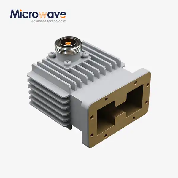 VIEW MOREHigh Power Waveguide to Coaxial Adapter
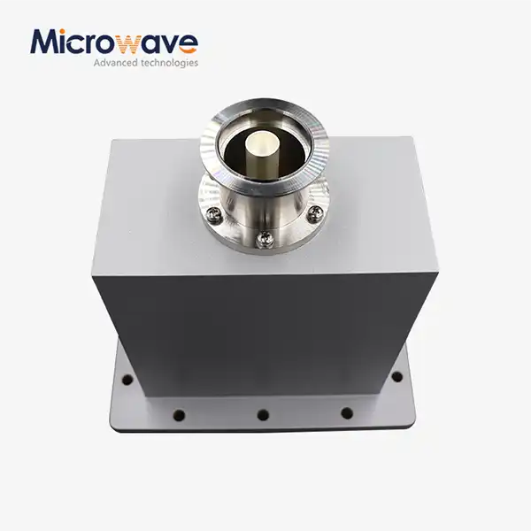 VIEW MOREEnd Launch Waveguide to Coaxial Adapter
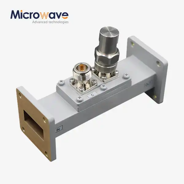 VIEW MOREWaveguide Loop Coupler
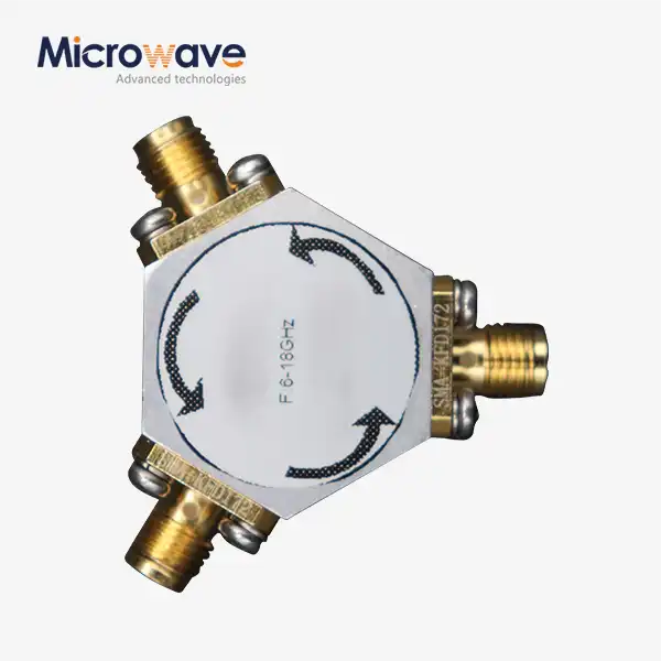 VIEW MOREBroadband Coaxial Circulator
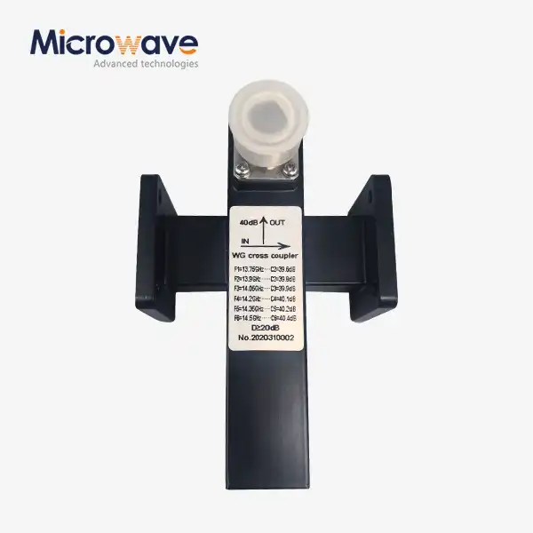 VIEW MORECrossguide Directional Coupler
 VIEW MOREDouble Ridge Straight Waveguide
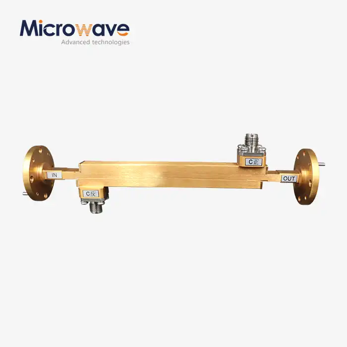 VIEW MOREDouble-Ridged Waveguide Broadwall Directional Coupler
 VIEW MORECoaxial Variable Attenuator