





WG Bandpass Filter Specifications Every Engineer Should Check
Some of the most important things to look for in a WG bandpass filter are its center frequency, passband width, insertion loss, return loss, stopband rejection, power handling, flange type, and steady temperature. I believe that every value should be seen as a guaranteed upper limit for the whole working range, not just as a normal number at the center frequency. It's possible that the rejection point is not where it should be, the flange does not fit, or the pulse power is too high. Filters may look good on paper, but they may not work in real life. This guide makes it easy to understand each check.
Introduction: Why WG Bandpass Filter Specifications Matter in RF and Microwave Systems
Where Waveguide Filters Fit
That stuff is used in radar, microwave links, satellite phones, wireless networks, antenna systems, and RF test gear. They don't lose much conductor or dielectric because they don't have a center conductor or dielectric. One that is well-built can reach a Q of between 2,000 and over 10,000 with no load. That means that even when the passband is very narrow, insertion loss can be less than 0.5 dB. There is a lot of power in the metal case, which also blocks the signal. This is the main reason engineers choose waveguides above 1 GHz, which is when heat and coaxial loss become problems.
Why Nominal Frequency Is Not Enough
"7.5 GHz" doesn't tell you much about the filter. It's possible for two parts with the same center frequency to have different passband widths, losses, rejections, and power ratings. We can tell from these differences whether the part keeps a receiver safe or lets noise get through. Integration is when most of the missing details show up, and it's also when redesigns cost the most. If you write down all of your needs before you ask for a quote, you can avoid most of these surprises. It also helps the supplier make a part that fits the first time.
How This Guide Is Organized
I did four types of checks: performance with electricity, limits on mass and power, fit between technology and application, and validation and purchase. Each group has numbers and short examples that you can use right away for your own needs. When you buy parts for defense, satellite, telecom, research, or OEM work, you should always do the same checks. The priority order is the only thing that changes when you send in your application.
Core Electrical Specifications of a WG Bandpass Filter
Center Frequency, Passband, and Passband Width
For a WG bandpass filter, first, find the level that sets the lower and upper passband limits. A lot of the time, this level is 1 or 3 dB. After that, make sure you know what frequency range is okay for each temperature and batch of production. The center frequency can be written as (f1 + f2)/2 or as the square root of f1 times f2. Let frequencies between 7.25 and 7.75 GHz go through. The arithmetic center is 7.5 GHz and the geometric center is about 7.496 GHz. Half of 7.5 is 0.5, which is about 6.7% of the whole. It takes about 15 to load the Q. Because Q goes up, manufacturing tolerances and tuning sensitivity get tighter. This makes the selectivity more accurate. Another thing it can do is make group delay for wide signals worse.
Insertion Loss, Return Loss, and VSWR
In this case, the power that the filter takes in inside the passband is known as insertion loss. Keep in mind that even a 0.5 dB drop in signal strength is about 11% less than it was before. This is a big deal in receiver chains and satellite links. Return loss and VSWR show it when you match. A VSWR of 1.3:1 is the same as a return loss of 17.7 dB, so you can compare datasheets that use different units. Never just look at these numbers in the middle of the passband. Check them all the way through. Band ripple and group delay are also things you should look at. Most of the time, phase response is just as important as amplitude when it comes to radar, broadband links, and fast data.
Stopband Rejection and Frequency Response
To help with rejection, it's helpful to have a list of exact frequency offsets and the least amount of attenuation at each one. With nearly stopband performance, channels next to you won't be able to hurt you. Far-stopband attenuation gets rid of harmonics and outside noise. More than 80 dB of out-of-band signals can be blocked by some waveguides. Waveguide filters have passbands that repeat at higher frequencies, like close to the second or third harmonic. Think about this. Sometimes, a low-pass filter section gets rid of those. The S-parameters for reflection are S21 and S11, and they should be given to you. Also, look at the different kinds of answers. While Butterworth, Chebyshev, elliptic, and Bessel all trade off flatness, roll-off, and phase linearity in different ways, they do so in different ways.
Mechanical, Power, and Durability Specifications
Waveguide Size, Flange, and Mechanical Fit
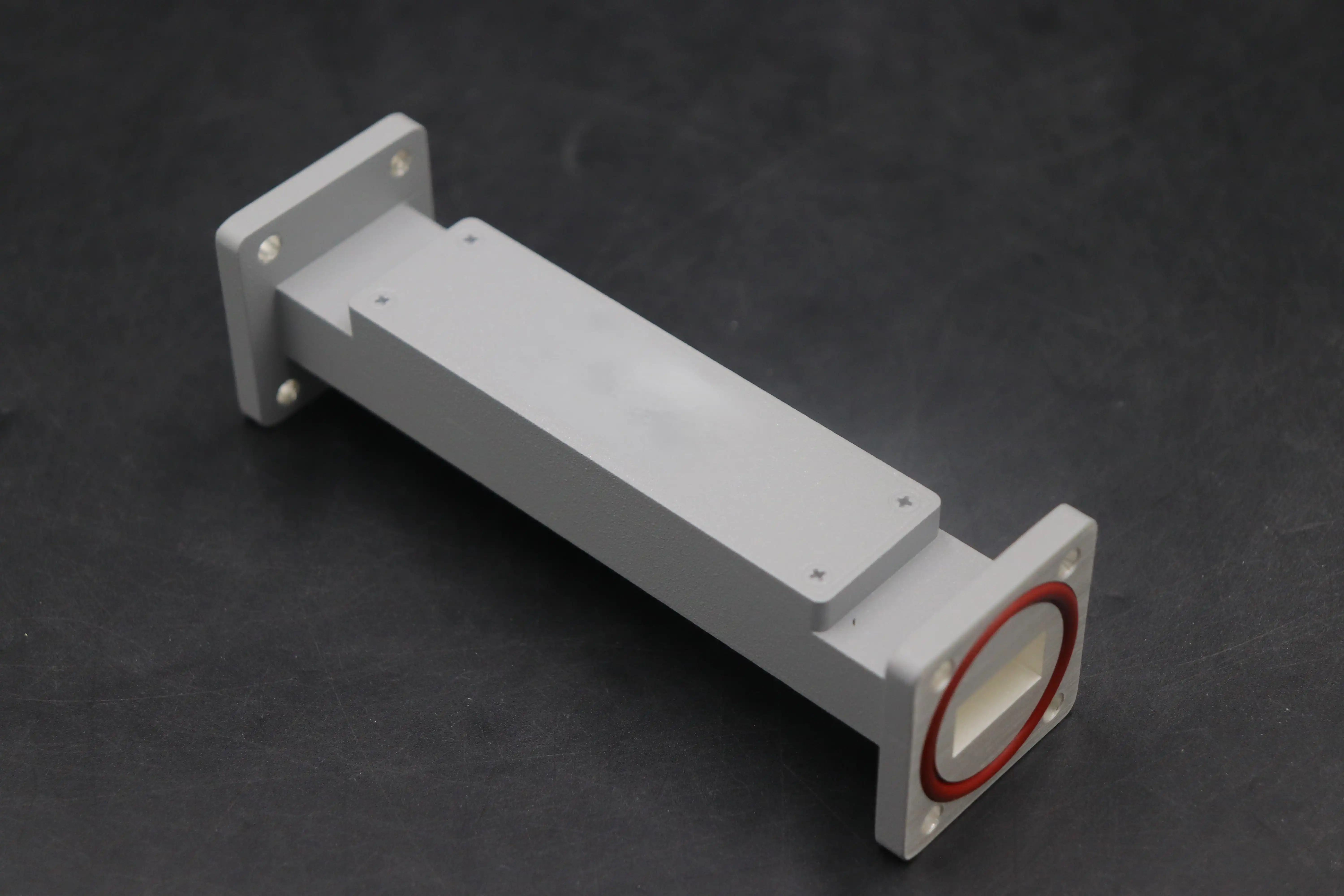
The electricity doesn't work right if the filter doesn't match the waveguide next to it. It is important to look at the waveguide's name, its internal size, its frequency range, its flange standard, its bolt pattern, its alignment pins, and how it seals. The WR-137 works between 5.85 and 8.2 GHz, and it is often paired with a CPR-137 flange in C-band systems. Million-wave parts often have this kind of flange. Leaks and reflections happen when the two don't match. Make sure you know the overall size, weight, space needed, mounting holes, and other details. Iron 6061, copper, and Invar are some of the materials that are used a lot. Because RF current flows in a thin layer on the surface, surface resistance goes down when you silver plate something. You need to sign off on the mechanical drawing before the parts are made.
Power Handling and Pulse Conditions
Power ratings are only useful if they match what you do for a living. In this case, we're interested in the average power, the peak pulse power, the pulse width, the duty cycle, and the reading rate. Average power is found by multiplying peak power by duty cycle. A 10 kW peak pulse gives off 10 W on average at 0.1% duty. Something that works well in a low-power receiver might arc or get too hot in a pulsed radar transmitter. The European space standard ECSS-E-20-01A talks about multipaction, which is a discharge effect that a space-payload filter has to deal with when it is empty. Find out what kinds of heights and air pressures the power rating works for.
Temperature Stability and Environmental Testing
For a WG bandpass filter, the center frequency goes down when metal gets hot because it expands. Invar, an alloy that doesn't expand much, and designs that change with temperature make the drift less noticeable. Set the largest shift that can happen across your whole range of operations. Don't just take one number for room temperature. For each site, you should ask for tests for temperature changes, vibration, shock, humidity, and salt spray. Sets that are outside or in the air usually need to be the strictest. The supplier can do the same job from one lot to the next if they can be tracked by serial number, keep records of calibration, and inspect each batch.
Technology and Application Selection
Waveguide Compared With Coaxial, Ceramic, SAW, and Cavity Filters
When in TEM mode, coaxial filters carry signals and are simple to connect to cables and plugs. They lose power and get too hot when the frequency and power are high. The ceramic and SAW filters are small and cheap, but they can't handle as many frequencies and powers. In the middle, you can find designs for cavities and dielectrics that are the right size, tune, and stable. Waveguide designs work best most of the time when you need a lot of power, good shielding, low conductor loss, or fine selection. I believe you should check the following numbers against the real ones: power, temperature, frequency, passband width, loss, rejection, volume, and package size. It's not just about the type of product that should matter.
Application Guide: SATCOM, Radar, and Backhaul
Satellite earth stations that use the C, X, Ku, and Ka bands can send and receive signals without mixing them. This makes sure that the receiver doesn't lose its sharpness. In radar systems, a WG bandpass filter gets rid of noise and harmonics from the amplifier output. The part needs to be able to handle a lot of peak pulse power without building up an arc. In the E band, waves move back and forth between 71 and 76 GHz and 81 and 86 GHz. The waveguide cleans up the signal enough for 256 QAM and other high-order modulations. The first rule is for SATCOM, the second is for radar peak power, and the third is for backhaul loss.
Defense, Research, and OEM Considerations
People who buy electrical parts for defense and aerospace often add traceability and documentation to the list. GPS, SDR, and receiver front ends all need low loss and strong out-of-band suppression. Being able to change things quickly and being flexible are more important in research labs where prototypes need to work with a wide range of frequencies. Manufacturers that add parts to other products need clear tolerances and paperwork that they can use in their own products. Some of the microwave parts that ADM sells are waveguide assemblies. These are used in navigation, defense, aerospace, and satellite communications. It uses these parts to find its way, keep an eye on the weather, build ships, and make unmanned aerial vehicles.
Procurement, Validation, and Supplier Selection
Building a Clear Request for Quotation
Quotes are done faster and don't have to be done again when you send a full request. Type of waveguide and flange, size, quantity, annual demand, stopband rejection points, ripple, group delay, power profile, temperature range, and the center frequency, passband limits, insertion loss, return loss, or VSWR. To get test reports, compliance documents, S-parameters, datasheets, drawings, and warranty terms from the supplier, you should have those things ready first. Look at how much each offer is worth all together. A small difference in price per unit isn't always worth the cost of engineering help, lead time, and the chance of failure.
Validating Samples Before Production Approval
Put prototypes of a WG bandpass filter to the test in places where they will be used in real life. To check the center frequency, passband width, insertion loss, return loss, ripple, and rejection, you can use a network analyzer that has been cleaned up. You can also add group delay and power tests if you need to. It is important to check the waveguide transitions and fixtures because they can change the results. Check the waveguide's size, how the flanges are lined up, where the bolt holes are located, the surface finish, and the opening. Then, make a list of limits that must be met in order to pass or fail, keep an approved "golden sample," and plan how to handle deviations and batch inspections. ADM has labs that can measure up to 110 GHz, which is in the range of millimeter waves.
Common Selection Mistakes
Most filter problems start with a specification that isn't complete. If you pick based on nominal frequency, you might not get rid of harmonics or channels that are next to each other. Leaks and delays in installation can happen when the flanges don't match up. Your normal values might not match the production limits that are guaranteed, so find out from the supplier what numbers they stand by. When teams forget to check the duty cycle, peak power, and temperature, the system may drift, arc, or fail before it should. It may also cost more in the long run to go with the lowest bid if the work isn't done right, documents are missing, lead times are too long, or replacements need to be made. This won't happen as often if the technical and business review are done at the same time.
Choosing a Custom WG Bandpass Filter Manufacturer
It will work if the frequency, passband, flange, power, and environment of a standard part match those of a prototype. Custom work is the best way to go when you need odd frequencies, narrow or wide passbands, stronger rejection, lower loss, high power, small packaging, or unique interfaces. The things you should do are learn about electromagnetic simulation, tuning, testing, prototypes, pilot runs, volume capacity, and OEM labeling. What are the pros and cons of Q, loss, rejection, size, cost, and tolerance? A good manufacturer will talk about these things. Engineering, machining, and plating take four to six weeks to finish a custom build that needs to be rejected in a certain way. They have worked with microwaves for more than 20 years and offer OEM services, prototyping, technical support, and quick turnover. These companies' goods are compliant with ISO 9001 and RoHS.
Conclusion
A WG bandpass filter only works well when all of the commercial, mechanical, electrical, and thermal needs are taken into account. When there is interference, it is important that the center frequency, passband width, insertion loss, VSWR, ripple, and rejection all match. You need to know about the waveguide size, flange type, materials, power rating, and temperature drift to know if the part will fit together and last its duty cycle. It is dependent on the use. Satcom likes rejection, radar likes peak power, and millimeter-wave backhaul likes low loss, among other things. It's less risky to redesign and buy something if you test samples against written limits, use guarantyd values instead of average values, and keep records that can be tracked.
FAQ
Q1: Which specification should I check first?
Check the 1 dB or 3 dB reference, the center frequency, and the passband limits first. Second, know the type of flange, the insertion loss, and the rejection points. These are the main things that determine fit and performance.
Q2: How do I convert VSWR to return loss?
Divide (VSWR - 1) by (VSWR + 1) to get the reflection coefficient. Then, multiply it by -20 times the logarithm in base 10. A VSWR of 1.3:1 gives about 17.7 dB.
Q3: When does a custom filter make sense?
If standard parts don't work for you in terms of frequency, loss, rejection, power, or interface, you should have one made just for you. Early on, let the supplier know everything they need to know so they can run simulations and make prototypes better.
Request a WG Bandpass Filter Quote From ADM
Any given frequency, rejection level, power profile, and flange type can be looked at by ADM, and the company will either suggest a standard part or make a WG bandpass filter just for you. ADM is a company that sells WG bandpass filters and has worked with microwaves for over 20 years. They do OEM work, prototyping, and technical support. Craig@admicrowave.com is a good place to send an email with your needs.
References
1. Microwave Engineering (David M. Pozar, Wiley), 2011
2. Microwave Filters, Impedance-Matching Networks, and Coupling Structures (Matthaei, Young, and Jones, Artech House), 1980
3. Microwave Filters for Communication Systems (Cameron, Kudsia, and Mansour, Wiley), 2018
4. Foundations for Microwave Engineering (Robert E. Collin, Wiley-IEEE Press), 2001
5. IEEE Std 1785.1, IEEE Standard for Rectangular Metallic Waveguides and Their Interfaces for Frequencies of 110 GHz and Above, 2012
6. ECSS-E-20-01A Rev.1, Multipaction Design and Test (European Cooperation for Space Standardization), 2020
YOU MAY LIKE
 VIEW MOREIndustrial Microwave Sliding Short
 VIEW MOREWaveguide E Bend
 VIEW MOREWaveguide Miter Bend
 VIEW MOREWaveguide Coupling Fixed Attenuator
 VIEW MOREWaveguide Sliding Short
 VIEW MOREDouble-Ridged Waveguide Loop Coupler
 VIEW MOREDouble-Ridged Waveguide Broadwall Directional Coupler
 VIEW MOREPyramid Horn Lens Antenna