Waveguide Terminator Performance and Power Handling Explained
Some inactive parts, called waveguide terminators, are very important. Their job is to soak up the electromagnetic energy that moves through RF and microwave waveguide systems. Its main job is to stop signal echoes that aren't needed and could make the system less stable, mess up measures, or damage sensitive gear. Things that are carefully picked out to take microwave energy turn it into heat. The most energy is lost, and the least amount is brought back into the system in this way. People who buy parts for defence, aerospace, satellite communications, and industry R&D need to know how they work at different power levels so they can choose the best one for mission-critical uses.
Understanding Waveguide Terminators: Definition, Working Principles, and Types
The Core Function and Operating Principle
Waveguide terminators are the endpoints of microwave communication lines. They stop standing waves and interference by absorbing electromagnetic waves. Unlike open-ended waveguides, which return almost all energy, terminators lose power internally by placing resistive or absorptive materials in the waveguide structure in a way that makes sense. Radio frequency power is changed into heat energy through dielectric or resistive losses. Power conversion. This process keeps the system's integrity by making sure that mirrored signals stay below critical levels that could damage nearby parts or measuring tools.
The level of match between the terminator and the waveguide's resistance shows how well it works. When it is paired right, the device makes it look like a tunnel that goes on forever and takes in almost all the power that comes in. One important way to judge the quality of a terminator is by its voltage standing wave ratio (VSWR). This impedance matching makes it as low as it can be. At the frequency they work at, high-performance terminators have VSWR values less than 1.05:1, which means their reflection coefficients are less than -40 dB.

Common Types and Their Industrial Applications
- Broadband Terminators: These flexible parts work with a lot of different frequency bands, which makes them perfect for test sets in the lab and multi-band transmission systems. Their design uses smooth changes in resistance to keep VSWR low over octave or multi-octave bandwidths. When working with frequency-agile test tools, research institutions often ask for broadband models.
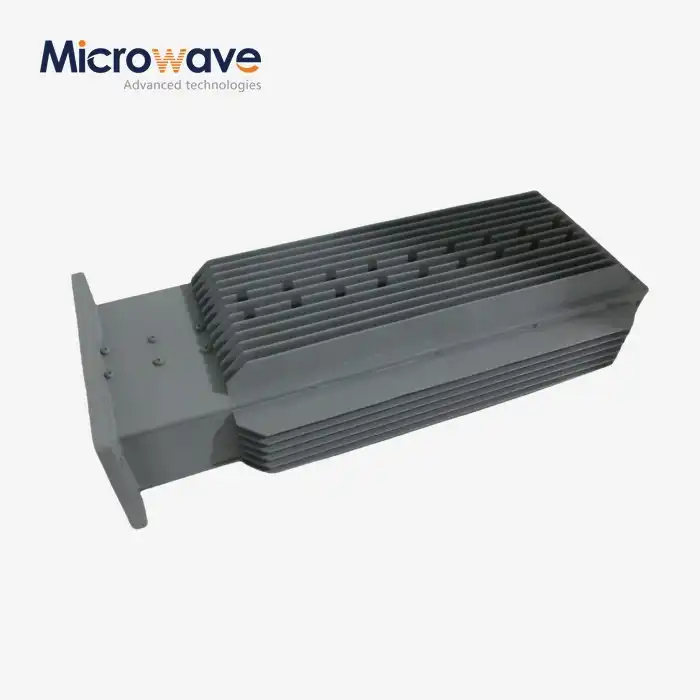
- High-Power Terminators: These terminators are designed for uses that need continuous or pulsed high-power transfer. They have better thermal management systems that include heat sinks, cooling fins, or liquid cooling interfaces. These strong designs are needed for defence radar systems and testing high-power transmitters because they can handle hundreds of watts of power all the time.
- Precision Measurement Terminators: These devices are designed to work best in measurement and calibration labs. They have very low VSWR and great reliability. Because they work the same even when the temperature changes, they are used as measures for calibrating vector network analysers and measuring antenna patterns.
- Terminators for specific frequencies (waveguide terminator): These parts work very well within certain frequency bands and were made for narrow-band uses like X-band satellite earth stations or Ka-band point-to-point lines. Their designed shape and materials let them handle the most power and return it the least in certain frequency ranges.
Performance Parameters and Power Handling Capabilities
Critical Electrical Specifications
The reflection coefficient tells us how much power bounces back from the terminator. It is given in decibels below the amount of power that first hit it. Good terminators keep their reflection coefficients at or below -30 dB, which means that less than 0.1% of the power that hits them is reflected. This standard is directly related to VSWR, and smaller numbers mean better speed. A VSWR of 1.2:1 means that the reflection coefficient is about -20.8 dB, which is fine for many commercial uses but not good enough for precise measurement settings.
Insertion loss isn't very important for waveguide terminator terminators because they're just ends, but it is important to look at waveguide loads that are used in power-measurement setups. The temperature coefficient of VSWR shows how stable performance is across working temperatures. This is especially important for outdoor setups or aircraft uses that go through extreme temperature changes.
Power Handling Fundamentals and Thermal Considerations
The strength of a waveguide terminator depends on how well it can turn incoming energy into heat without heating the material too much or changing how well it works electrically. Standard terminators can handle power levels that stay the same from 1 to 50 watts, which is enough for low-power test jobs and following signals. For short times, high-power models can boost this range to a few hundred watts or even kilowatts. This is what is needed to test antennas and put radar systems together.

Controlling the temperature is very important when there is a lot of power. Most of the time, the absorptive element is made of clay or a mix of clay and carbon. It gives off heat equal to the power it takes in. When there aren't enough heat sinks, temperatures inside can rise quickly, which could cause materials to break down, VSWR to drop, or a catastrophic failure. We've seen in the field that a 100-watt terminator that isn't properly cooled can get too hot to handle in just a few minutes of continuous use.
The material used has a big effect on the power flow. High-power continuous-wave uses work really well with silicon carbide ceramic terminators because they are better at moving heat around and staying stable at high temperatures. Epoxy materials with carbon added are less expensive for low power levels, but they need to be carefully thermally constructed to avoid fires. When the power level goes above 25 watts, metal-film resistance elements need to lose a lot of heat. They work well in small shapes.
When you put a regular 10-watt X-band terminator next to a high-power 200-watt one, these thoughts become clear. It's about 50 mm long and has a simple metal base that serves as both a frame and a heat sink. At normal temperatures, its carbon composite absorber can only handle 10 watts of steady power. However, it can safely work in temperatures up to 150°C. It has a copper heat spreader, a metal case with fins, and a heat-absorbing form that is made for 150mm of power. With forced air cooling, this system keeps temperatures at 200 watts of steady power, which is safe for work. This means it can be used for more tasks, like checking receivers with fake loads and checking the size of strong antennas.
Long-Term Reliability and Degradation Mechanisms
Thermal cycling over and over again can put stress on waveguide terminator materials, which could lead to mismatched growth, bond failure, or changes in the material's properties. Accelerated life testing shows that high-quality parts keep their VSWR performance fixed over thousands of heat cycles. Knowing these traits of reliability helps buying teams choose parts with the right derating factors, which protects system stability in mission-critical installs.
Comparing Waveguide Terminators: Making the Right Choice
Material Comparisons and Performance Trade-offs
Ceramic-based terminators dominate high-reliability applications where temperature stability and long-term performance predictability matter most. Aluminium oxide and silicon carbide ceramics maintain consistent electrical properties across wide temperature ranges, resisting degradation from humidity and thermal stress. These materials support high power densities, making them preferred choices for compact designs. Their brittleness requires careful mechanical design, but properly engineered ceramic terminators deliver decades of reliable service in demanding environments.
Carbon composite alternatives blend carbon particles or fibres within epoxy or polymer matrices, creating absorptive structures at lower manufacturing costs. These materials shape easily into complex geometries, enabling broadband impedance matching and compact packaging. Their primary limitation involves temperature sensitivity—electrical properties drift with thermal cycling, and sustained high temperatures can cause permanent changes. Carbon composites fit well in moderate-power applications where cost optimisation and design flexibility outweigh ultimate performance.

Metal-film resistive terminators position thin resistive films on thermally conductive substrates, achieving excellent electrical performance in miniature packages. This approach supports precision VSWR control and compact integration but requires substantial external heat sinking for meaningful power handling. Aerospace and defence applications value their repeatability and radiation resistance.
Frequency Band Selection and X-Band Specifics
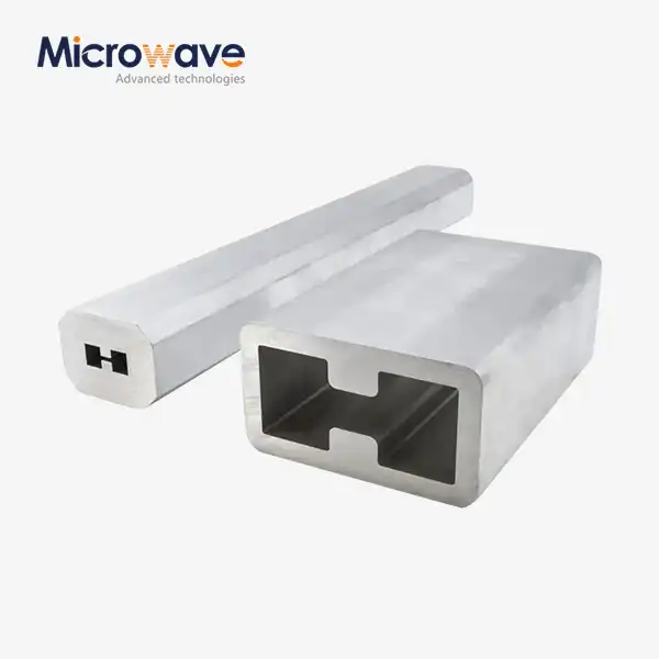
X-band systems operating between 8.2 and 12.4 GHz represent a sweet spot in microwave technology, widely deployed in radar, satellite communications, and defence applications. Terminators for this band balance manageable physical dimensions with achievable precision manufacturing tolerances. A standard WR-90 rectangular waveguide terminator for X-band measures roughly 23mm x 10mm in cross-section, accommodating compact installations while providing sufficient volume for power dissipation.
Selecting terminators for higher frequency bands like Ka-band (26.5-40 GHz) introduces manufacturing challenges due to reduced physical dimensions and tighter tolerance requirements. Lower frequency bands such as S-band (2-4 GHz) offer easier manufacturing but result in bulkier components. Understanding these trade-offs helps procurement teams align component selection with space constraints, performance requirements, and budget parameters.
Terminators versus Dummy Loads and Attenuators
Although related, these components serve distinct purposes that sometimes confuse procurement specifications. Waveguide terminators function purely as absorptive endpoints, designed to eliminate reflections with no signal output. Dummy loads perform a similar absorption function but often include power measurement capabilities and cooling systems optimised for transmitter testing. Terminators emphasise low VSWR and compact packaging, while dummy loads prioritise high average power handling and sometimes include integral wattmeters.
Attenuators differ fundamentally by providing controlled signal reduction with a through-transmission path. Where a waveguide terminator might achieve -40 dB reflection, an attenuator passes most power to its output port while dissipating a predetermined fraction. Confusion arises when specifying "loads" for test setups—clarifying whether the application requires complete absorption or measured through-transmission prevents costly procurement errors.
Conclusion
Selecting the right waveguide terminator balances electrical performance specifications, including VSWR and power-handling capacity, against practical considerations like thermal management, environmental durability, and lifecycle costs. Understanding how materials and design choices influence these characteristics empowers procurement teams to specify components matching application requirements without over-engineering or cost overruns. The global market offers diverse suppliers with varying strengths—leveraging established manufacturers' expertise while exploring specialised suppliers for custom requirements optimises both performance and value. Proper installation, systematic testing, and disciplined maintenance preserve the investment in quality components, ensuring long-term reliability in mission-critical systems.
FAQ
1. What factors most significantly impact waveguide terminator power handling capacity?
Material thermal conductivity determines how efficiently heat moves from the absorptive element to the heat sink. Design geometry influences power density—larger absorptive volumes distribute heat across greater mass. External cooling provisions like fins, forced air, or liquid cooling extend power capacity substantially. Operating duty cycle matters greatly, as pulsed applications tolerate much higher peak power than continuous-wave operation at equivalent average levels.
2. Can waveguide terminators substitute for waveguide loads in all applications?
The terms often describe similar components, but loads typically emphasise high power handling with integral cooling systems, sometimes including power metres. Terminators prioritise low VSWR and compact packaging. For low-power lab measurements and system endpoints, terminators work perfectly. Transmitter testing and high-power dummy load applications need components specifically designed for sustained power dissipation.
3. What lead times should we expect for custom terminator orders?
Custom designs typically require 8-12 weeks from specification approval through delivery. This timeline includes engineering design validation, prototype fabrication, electrical and thermal testing, and production runs. Expedited programmes compress schedules to 4-6 weeks with premium pricing. Standard modifications like flange changes complete faster than full custom designs requiring new tooling. Clear specification definition at project start minimises revision cycles that extend schedules.
Partner with ADM for Your Waveguide Terminator Requirements
Advanced Microwave Technologies Co., Ltd brings over 20 years of specialised experience as a trusted waveguide terminator manufacturer and supplier, serving demanding applications across defence, aerospace, satellite communications, and industrial research sectors. Our comprehensive product portfolio spans standard catalogue components for immediate delivery and fully custom solutions engineered to your exact specifications. Every terminator undergoes rigors testing in our ISO 9001-certified laboratories equipped with measurement capabilities extending to 110 GHz, ensuring performance validation before shipment.
We understand that B2B procurement demands more than just components—you need reliable partners committed to your success. Our technical team collaborates closely with your engineering staff, providing application support from initial specification development through installation and commissioning. Whether you require ruggedized X-band terminators for airborne radar systems or precision reference terminators for calibration laboratories, we deliver proven solutions backed by comprehensive documentation and responsive after-sales support. Contact craig@admicrowave.com to discuss your requirements with our specialists, request detailed datasheets, or obtain personalized quotations for waveguide terminator solutions that power your critical systems with confidence.
References
1. Pozar, David M. "Microwave Engineering, Fourth Edition." John Wiley & Sons, 2011.
2. Collin, Robert E. "Foundations for Microwave Engineering, Second Edition." IEEE Press, 2001.
3. Rizzi, Peter A. "Microwave Engineering: Passive Circuits." Prentice Hall, 1988.
4. Saad, Theodore S. "Microwave Engineers' Handbook, Volumes 1 & 2." Artech House, 1971.
5. Harvey, A.F. "Microwave Engineering." Academic Press, 1963.
6. Montgomery, C.G., Dicke, R.H., and Purcell, E.M. "Principles of Microwave Circuits." MIT Radiation Laboratory Series, McGraw-Hill, 1948.