Waveguide Fixed Attenuator Specs Decoded: VSWR, Flatness, Tolerance
If you work in RF system design or microwave component procurement, you already know that choosing the wrong attenuator can quietly destroy system performance. A waveguide fixed attenuator reduces signal power by a preset decibel value without altering waveform shape or phase — but its real-world performance depends entirely on three specifications: VSWR, frequency flatness, and attenuation tolerance. Getting these numbers right separates a system that performs from one that fails under load. This guide breaks down each parameter clearly, so you can read datasheets with confidence and source components that actually meet your requirements.
Understanding the Core Specifications of Waveguide Fixed Attenuators
These three factors determine whether a fixed attenuator will work reliably in your system or cause issues that will take weeks to figure out.
VSWR: What It Means and Why It Matters
The Voltage Standing Wave Ratio (VSWR) shows how well the resistance of an attenuator fits the transmission line. If the VSWR is 1.0:1, there should be no signal bounce. In real life, good waveguide fixed attenuators keep the VSWR below 1.20:1 across their whole working range. Models made for metrology can get VSWR ≤ 1.10:1. When VSWR is bad, power is reflected back into the system. This can lead to mistakes in measurements, oscillator frequency shifting, and, in high-power situations, damage to upstream parts like solid-state amplifiers.
Frequency Flatness: Consistency Across the Band
Flatness is a measure of how stable the attenuation is over the whole frequency range. A standard-grade attenuator might change by ±0.5 dB, but a precision unit stays within ±0.2 dB. Even a 0.3 dB shift in the middle band can mess up measurements of gain compression in calibration labs that test 5G millimeter-wave parts or phased array radar modules. When it comes to frequency bands, the attenuator does its job better everywhere when the response is flat.
Attenuation Tolerance: Permissible Variation from Nominal
Tolerance tells you how close the real attenuation is to the value that was labeled. IEEE standards say that tolerance should be between ±0.3 dB for low-value attenuators (1–3 dB) and ±1.0 dB for high-value attenuators (20 dB and above). In radar calibration, satellite uplink tracking, and test instruments, where signal level accuracy directly affects measurement validity, tolerances need to be tighter. Before making an order, you should always compare the tolerance requirements to the link budget for your system.
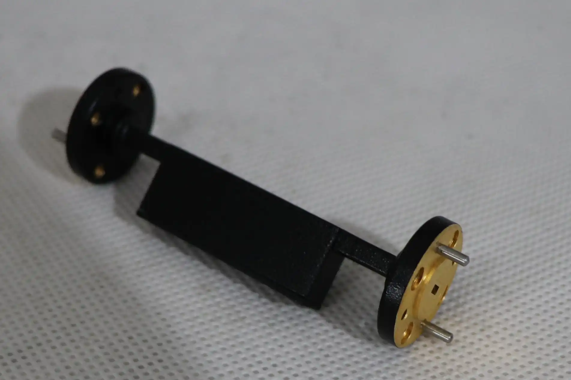
Comparative Analysis: Waveguide Fixed Attenuator vs Other Attenuator Types
To choose the right reduction technology, you need to know what the pros and cons are. You can see how waveguide fixed attenuators stack up against three other popular options below:
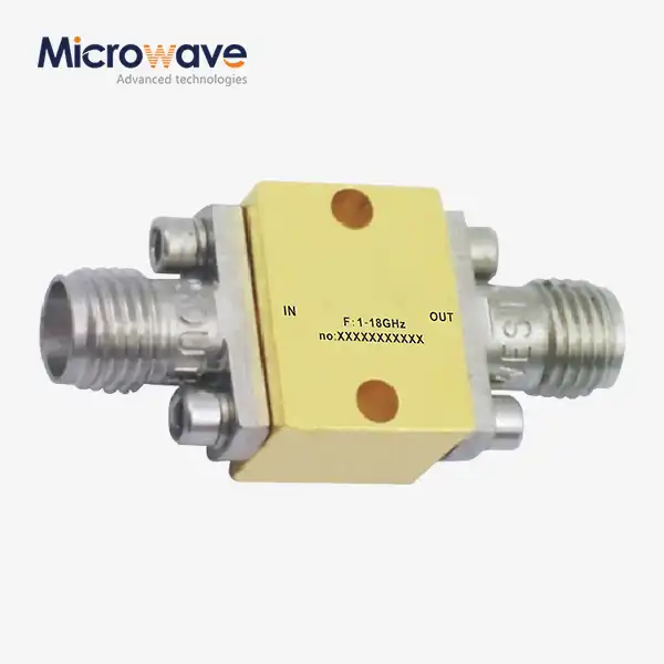
- Coaxial Fixed Attenuators are good at lower microwave frequencies (usually less than 18 GHz) and come with a variety of connection choices. But when the frequency goes above 26.5 GHz, skin-effect losses get worse, and connector repeatability problems happen more often with coaxial designs. Waveguide fixed attenuators get around these problems by using a hollow metal structure with a resistive vane that stays mechanically stable above Ka-Band.
- Variable Attenuators let you change the level of attenuation, which is good for uses that need to change the signal level a lot. In exchange, they have worse VSWR performance and can't handle as much power as fixed waveguide systems. Variable types also add uncertainty to the insertion loss, which gets worse over time as the tuning element wears down from mechanical wear.
- PIN Diode Attenuators can switch electronics quickly, making them good for digital beamforming and pulsed radar systems. But their VSWR performance depends a lot on bias, and they need active control hardware that costs more and has more places where things can go wrong. They aren't good for tasks that need to passively block high-power CW signals.
Waveguide fixed attenuators are still the best choice when you need stable, repeatable reduction at high power levels and high frequencies, and you don't want to have to deal with any moving parts.
Key Technical Specs Breakdown for Procurement Managers and Engineers
It takes time to read a microwave component datasheet properly. Before you sign a buy order, make sure you do these things.
Frequency Range and Waveguide Size Selection
The waveguide band is based on the operating frequency. WR-90 is used for X-Band (8.2–12.4 GHz), WR-62 is used for Ku-Band (12.4–18 GHz), WR-28 is used for Ka-Band (26.5–40 GHz), and WR-10 is used for W-Band (75–110 GHz). When you use the wrong waveguide size, you can get cutoff conditions or higher-order mode transmission, which you won't see in a document but will clearly show up as system failure.
Power Handling: Average vs. Peak
Thermal dissipation, or how well the resistive element moves heat to the body and the air around it, limits the average power (CW). Arcing, or voltage breakdown, inside the waveguide chamber limits the peak power. These limits stand on their own. Just because a part can handle 50W peak pulses doesn't mean it can handle 50W average power. For burst radar or high-power SATCOM uses, make sure both numbers are correct.
Benchmark Values From Established Manufacturers
For standard commercial waveguide fixed attenuators, top brands like Pasternack, Narda, and Keysight usually list VSWR ≤ 1.15:1 and flatness within ±0.3 dB. To meet the MIL-DTL-3933 standards, parts are put through tougher tests that check for electrical and chemical problems. Use these published benchmarks as a starting point when comparing quotes from different suppliers to see if a cheaper option actually meets the requirements.
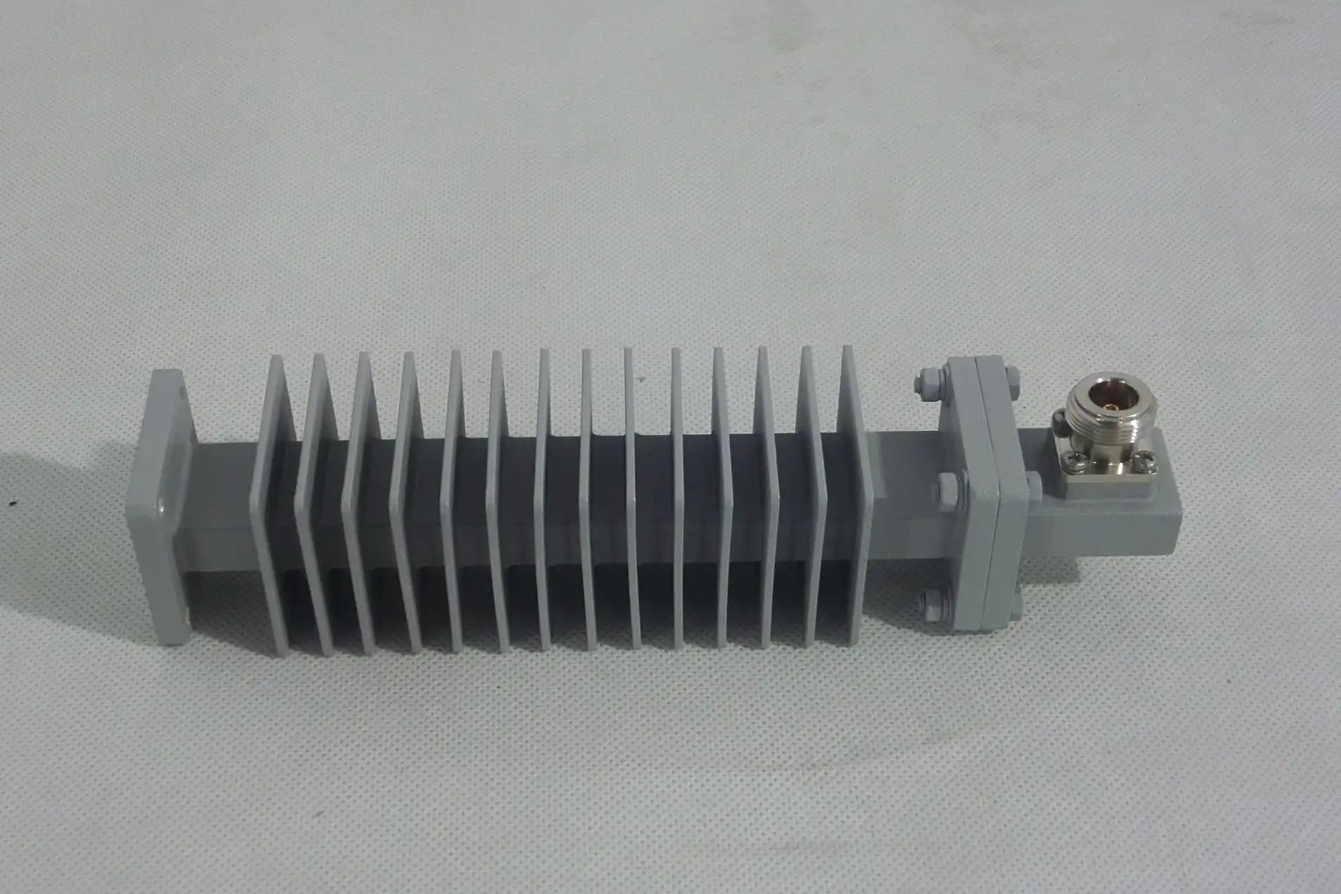
Practical Applications and Procurement Considerations
Waveguide fixed attenuators are used in three high-stakes situations where exact specifications must be met.
In SATCOM earth stations, they lower the HPA output from kilowatts to milliwatts, which is safe for spectrum monitors to use during loopback tests. In defense radar Transmit/Receive modules, they take in power that is returned because of antenna mismatches. This keeps the signal source safe from standing waves that can damage it. In precise microwave test labs, the output of a high-gain amplifier is lowered into the linear range of measured power monitors. This is necessary for accurately characterizing 5G and 6G parts.
When buying these parts, procurement teams should think about a number of real issues. Standard waveguide bands usually have lead times of two to six weeks from stock. For special frequency ranges or non-standard flanges, the lead time could be eight to twelve weeks. When you buy more than 50 units, the cost per unit is often cut by 10–20% through bulk purchasing agreements. You can get specialty items with a MOQ as low as one unit, but they will cost more. Examples of these are W-Band and custom power ratings. Which material you choose—Oxygen-Free Copper, Aluminum 6061, or copper plated in silver or gold—affects both function and cost. Before you order, make sure that the flange standards (UG, Cover, or Choke) fit the waveguide gear you already have.
Ensuring Specification Compliance and Long-Term Performance
Specification compliance starts at the factory and lasts as long as the part is used.
Recommended Quality Control Tests
Before shipping, tests with a vector network analyzer (VNA) should be made to check the attenuation accuracy, VSWR, and power handling. Each unit from a reputable manufacturer comes with full S-parameter data. Thermal stability testing, which usually gives high-quality materials like Silicon Carbide absorbers a rating of less than 0.005 dB per degree Celsius, proves performance under temperature cycling conditions that are common in radar and aircraft settings outside.
Certification Standards to Require
MIL-DTL-3933 tells waveguide fixed attenuators used in defense systems what they need to be electrically and environmentally. At the production level, ISO 9001:2015 certification means that quality control processes can be tracked. Always ask for a certificate of conformance (CoC) and, if needed, a testing certificate that can be tracked back to NIST standards.
Preventing Performance Drift Over Time
Most of the time, attenuation drift is caused by flange surface oxidation, waveguide connections coming loose, and thermal cycling breaking down the absorber material. Cleaning flanges with isopropyl alcohol, tightening flange bolts to the right torque (as directed by the manufacturer), and storing parts in a dry, temperature-controlled area all make them last longer.
Conclusion
A waveguide fixed attenuator either works as expected or becomes a problem in your RF system based on three specs: VSWR, frequency flatness, and attenuation tolerance. System breakdowns that cost a lot of money can be avoided by carefully reading datasheets, making sure that waveguide size matches working frequency, and checking power handling limits before buying. Your procurement process will be more reliable if you buy from manufacturers who provide test data that can be tracked and allow open sharing of specifications.
FAQ
What VSWR should I expect from a quality waveguide fixed attenuator?
The VSWR for standard industrial-grade is usually less than 1.20:1. VSWR ≤ 1.10:1 is reached by precision or metrology-grade waveguide fixed attenuators. The tighter the VSWR, the less reflected power hurts nearby parts.
How does attenuation tolerance affect radar system calibration?
In radar systems, a tolerance error of ±1.0 dB in a calibration attenuator means that measurements of the target cross-section are also ±1.0 dB uncertain. When calibrating defense-grade radar, you usually need a tighter range of ±0.3 dB or better.
Can I request a custom frequency range or power handling level?
Yes. Most well-known companies that make waveguide fixed attenuators will take special orders for frequency bands, attenuation values, flange configurations, and power levels that aren't standard. Prices and lead times change based on how complicated the design is.
Are these attenuators bi-directional?
They work in both directions for most waveguide fixed attenuators because they are balanced. For uses that need a lot of power, make sure that the heat-sink design doesn't favor one way of orienting the input ports.
How do I choose between WR-90 and WR-28?
The selection is based on the operating frequency. WR-90 works with the X-Band (8.2–12.4 GHz), and WR-28 works with the Ka-Band (26.5–40 GHz). When sizes don't match, shutdown conditions occur that stop the information from spreading at all.
Partner With ADM for Precision Waveguide Fixed Attenuators
ADM makes waveguide fixed attenuators that meet strict standards for VSWR, flatness, and tolerance. These are checked with full S-parameter test data and come in standard and custom configurations for X, Ku, Ka, and W-Band. ADM is a reliable supplier of waveguide fixed attenuators, and they help procurement teams by providing datasheets, CoC documentation, and direct engineering consultation. To get a price right away, email our team at craig@admicrowave.com.
References
1. Pozar, D. M. Microwave Engineering, 4th Edition. Wiley, 2011.
2. MIL-DTL-3933 — Detail Specification: Attenuators, Fixed and Variable, Radio Frequency. U.S. Department of Defense, 2003.
3. Rizzi, P. A. Microwave Engineering: Passive Circuits. Prentice Hall, 1988.
4. IEEE Standard 287-2007: IEEE Standard for Precision Coaxial Connectors at RF, Microwave, and Millimeter-Wave Frequencies. IEEE, 2007.
5. Montgomery, C. G., Dicke, R. H., & Purcell, E. M. Principles of Microwave Circuits. MIT Radiation Laboratory Series, McGraw-Hill, 1948.
6. Agilent/Keysight Application Note 1287-3: Applying Error Correction to Network Analyzer Measurements. Keysight Technologies, 2014.