Waveguide Crossguide Coupler Design and Performance Analysis
Waveguide crossguide couplers represent critical components in microwave applications, enabling efficient signal distribution and power monitoring within waveguide systems. At Advanced Microwave Technologies Co., Ltd (ADM), we've observed that understanding crossguide coupler design and performance characteristics remains essential for procurement professionals tasked with sourcing reliable, high-quality components. This comprehensive guide is crafted for purchasing managers, engineers, distributors, and OEM clients in industrial sectors, emphasizing how detailed design insights and performance analysis drive better decision-making. By aligning technical requirements with procurement strategies, stakeholders can minimize risks, optimize budgets, and ensure compatibility with system specifications across diverse applications ranging from radar installations to satellite ground stations.
Understanding Waveguide Crossguide Couplers
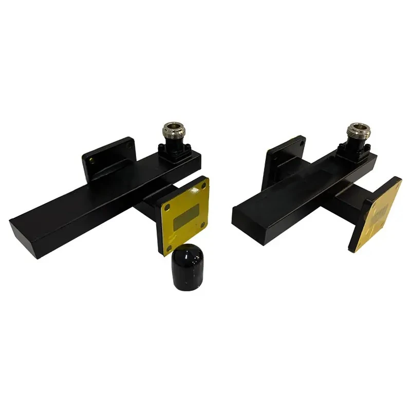
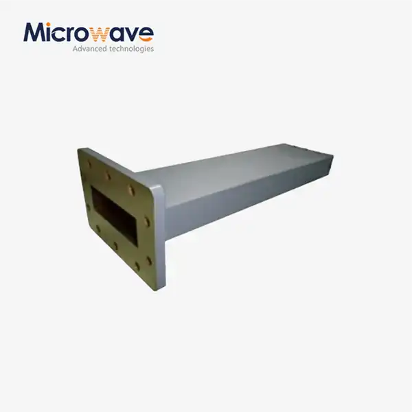
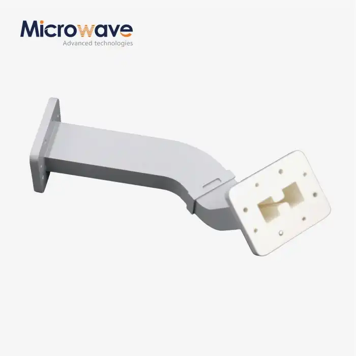
A crossguide coupler has two waveguide sections that are placed at right angles to each other. These sections are the main transmission line and the secondary sample arm. Energy moves from the main waveguide to the secondary branch through precise holes in the broad wall where the two guides meet. The crossguide coupler setup is designed to be small, while parallel broadwall couplers depend on contact over long distances to achieve high directivity and bandwidth. This orthogonal design directly solves the important problem of signal tracking in limited space, which is especially useful in complicated radar feed networks and satellite payloads where space is at a premium.
Operating Principles and Role Within Systems
Electromagnetic fields are coupled through carefully measured slots or cruciform holes to make the basic process work. A controlled amount of the RF energy that moves through the main waveguide goes through these holes and into the parallel auxiliary guide. The way the two parts are connected depends on the shape of the aperture, the size of the waveguide, and the frequency being used. This sampled signal lets you measure power, set the default level, and find faults without interfering with the main transmission line too much. Engineers like this feature because it lets them keep an eye on the system in real time while keeping the main channel's data integrity.
Common Types and Performance Specifications
It is possible to get crossguide couplers with three or four ports. Three-port versions have an internal matching termination on the separated port, which makes putting the system together easier. Four-port bidirectional versions need an external end, but let you check both forward and mirrored power at the same time. Some important performance specs are coupling factor (usually between 10 and 40 dB), directivity (usually between 18 and 25 dB), frequency range (based on waveguide band like WR-90 or WR-284), insertion loss (usually less than 0.3 dB), and VSWR (usually less than 1.25:1). When purchasing things, people need to carefully compare datasheets to what the job calls for. They need to keep in mind that the accuracy of the connection has a direct effect on the accuracy of measurements in ALC loops and power monitoring circuits.
Comparison With Alternative Coupling Technologies
Crossguide coupler designs have a much smaller physical size than multi-hole directional couplers, but they have a shorter operational bandwidth and less directivity. Multi-hole couplers have directivity greater than 40 dB because they cancel out phase at multiple coupling points. This makes them better for uses that need extreme isolation. Magic tees work completely differently; they split power evenly with specific phase relationships instead of sampling a small part. When small size, middling directivity, and strong power handling are all important, the crossguide coupler method works best. When procurement teams understand these trade-offs, they can better match the features of components with the needs of the system architecture.
Design Principles and Performance Optimization
To make crossguide couplers that work well, you need to be very careful with the waveguide size, the materials you use, and the shape of the coupling slots. These all have a direct effect on the frequency response, isolation, and power handling. The most important part is the design of the coupling aperture. Its form, size, location, and direction affect the coupling strength and frequency dependence. In some designs, cruciform apertures offer higher bandwidth, while rectangular slots offer known coupling properties. Isolation is affected by the width of the walls between waveguides that cross each other. If the walls aren't thick enough, unwanted leaking happens, which lowers the directivity.

Material Selection and Mechanical Precision
The choice of material affects both how well it works electrically and how well it works mechanically. Aluminum metals have great strength-to-weight ratios for use in the air, while copper or brass is better at conducting electricity and having a high heat capacity, making it the best choice for high-average-power systems on land. Surface plating, usually with silver or gold, lowers skin effect resistance, which lowers insertion loss. Tolerances in manufacturing have a big impact on performance. The rim must be flat, and the apertures must be lined up correctly according to MIL-DTL-3922 standards to stop RF leaks or voltage breakdown when the power is high. At ADM, we can machine parts to standards of less than 0.001 inches, which ensures that the electrical properties stay the same from one production run to the next.
Optimization Strategies for Enhanced Performance
Some common design problems are too much insertion loss, not enough directivity, and a low frequency. The first step in optimization is to simulate electromagnetic fields and how they interact with each other using HFSS or CST Microwave Studio. By making small changes to the aperture geometry over and over, the coupling strength and bandwidth needs can be balanced. Pay close attention to junction discontinuities and waveguide changes in order to minimize leakage. Impedance-matching stubs close to coupling openings and carefully placed absorptive materials to block spurious modes are examples of more advanced methods. Before full-scale production, testing high-power samples in real-world settings confirms their heat performance and finds places where they might break down. These strict development methods let companies like ADM make parts that meet tough operating needs in the defense, aircraft, and telecommunications sectors.
Comparison and Selection Criteria for Crossguide Couplers
To choose the right crossguide coupler, you need to know the differences between crossguide and other waveguide coupling technologies and weigh things like performance, cost, and the application you want to use it for. Crossguide coupler designs work great when you need small packaging with middling directivity (18–25 dB is common). Radar transmitter tracking uses real-time power sampling to tell automatic level control circuits what to do, and satellite uplink stations let operators send test signals without stopping contacts. Multi-hole directional couplers, on the other hand, are better for broadband tracking tasks that need directivity above 40 dB but can handle longer insertion lengths.
Efficiency and Power Handling Benchmarks
Waveguide size, pressurization, and opening shape all affect how much power they can handle. In pulsed radar uses, standard WR-90 crossguide couplers can handle peak powers of more than 100 kW, while bigger WR-284 units can handle several hundred kilowatts. The main problem is the breakdown voltage at the coupling slots; good design keeps field intensities below the ionization thresholds. Usually, less than 0.3 dB of insertion loss means more than 93% efficiency, which is good enough for most tracking tasks. When evaluating reliability, it's important to look at things like thermal cycling, vibration exposure, and the need for environmental sealing. According to military standards, equipment must be able to work in temperatures ranging from -55°C to +85°C and be resistant to humidity. This calls for tough construction with airtight seals.
Correlating Technical Specifications With Procurement Constraints
It can be hard for business-to-business buyers to match up technical datasheets with their budget, delivery schedules, and needs for customization. Standard catalog parts have shorter lead times and lower unit costs, but they might not work perfectly with your system. Custom designs let you get the best performance for certain frequency ranges, coupling values, or mechanical connections, but they take longer to build and cost more. When procurement teams look at the total cost of ownership, they should not only look at the unit price but also at how hard it is to integrate, how many tests are needed, and how reliable the system will be in the long run. As ADM's technical team does with all of its clients, getting involved with manufacturers early in the planning process lets them work together to come up with solutions that balance efficiency and cost-effectiveness. Prototyping services let you test your ideas before committing to large quantities of production, which lowers both the technical and financial risk.
Procurement Guide: Sourcing and Buying Crossguide Couplers
To find your way around the global market for crossguide couplers, you need to find the top makers in the US, Europe, and Asia and learn about their names, customer service, and quality systems. Established suppliers keep their ISO 9001 certification, which shows that they manage quality in a systematic way, and RoHS compliance, which shows that they care about the environment. To figure out how reliable a provider is, you need to look at their list of certifications, their guarantee policies, and customer references. Technical validation can be done before a purchase is made by asking for detailed datasheets with full S-parameter measurements across certain frequency ranges.
When you buy tens or hundreds of units at a time, you can usually get price breaks. These discounts range from 10 to 30 percent. You can change more than just the coupling values and frequency ranges. You can also change the mechanical connections, mounting arrangements, and weather ratings. Catalog items may ship within two weeks, but unique designs can take anywhere from eight to sixteen weeks, based on how complicated they are. When sending goods internationally, it's important to make sure they are properly packaged to protect them from shocks and vibrations, that the right Incoterms are used, and that all import and export paperwork is complete. ADM has been exporting goods around the world for more than twenty years, so they can easily deliver to customers in different countries and make sure that the technical paperwork meets all the different legal needs.
Sample testing is a smart way to buy things, especially when dealing with new suppliers or important uses. By asking for engineering samples, you can test the electrical performance, mechanical fit, and build quality in-house before committing to large orders. When you look at costs, you should not only look at unit prices, but also shipping, customs taxes, and the possible costs of delays in merging if parts don't work right. Framework agreements with preferred suppliers set pricing structures, quality expectations, and escalation procedures. This makes future purchases easier and builds strategic partnerships.
Applications and Future Trends in Waveguide Crossguide Couplers
There are many places where crossguide couplers are used, such as in radar sites, satellite systems, internet infrastructure, and industrial microwave processing. In the world of telecommunications, they allow power monitoring in terrestrial microwave links and wireless backhaul networks, which protects the quality of signals over long distances. Crossguide couplers are used in a wide range of radar systems, from air traffic control to weather tracking, to sample the power coming from the sender and feed it into automatic level control loops that keep the pulse output steady despite changes in temperature and the aging of the equipment. Satellite ground stations use these parts in high-power transfer chains. The operators of these chains have to keep an eye on the forward power and find the reflected energy from antenna mismatches.
Industrial and Defense Applications
In order to distinguish between forward and reflected power in industrial microwave heating systems, crossguide couplers are used. This keeps expensive magnetrons from getting damaged by changes in load impedance. For defense uses like monitoring radars, electronic warfare systems, and communication networks, it's important that they are small and work well in harsh circumstances. Naval systems like ADM's maritime-rated parts are made with tough materials and metal that doesn't rust. This makes sure that the parts work well in the damp, salty environments that are common on ships.
Emerging Trends and Future Directions
Crossguide coupler technology keeps getting better thanks to new materials, ways for making things smaller, and the ability to work with computer control systems. With additive manufacturing, it's possible to make parts with complex internal geometries that weren't possible with traditional machining. This could increase bandwidth and decrease size. Modern dielectric materials with specific qualities make it easier to handle power and keep temperatures down. Integration with IoT platforms lets you check on coupler performance data from afar, which helps with planned repairs and lower system downtime. In the future, millimeter-wave applications for 5G backhaul and beyond will need couplers that work at W-band frequencies (75–110 GHz), which will make manufacturing more precise and measurement more accurate. Buying plans should take these changes in technology into account, making sure that the parts bought can still work with new system designs and have useful lifetimes that are measured in decades instead of years.
Conclusion
Waveguide crossguide couplers are small devices that can analyze signals and keep an eye on power levels. They are perfect for microwave systems that don't have a lot of room. Knowing about design principles, performance trade-offs, and selection criteria helps procurement workers find parts that meet technical needs while minimizing costs and speeding up delivery times. The comparison of crossguide and other coupling technologies makes it clear which ones are best for which applications. The procurement guidance talks about how to choose a supplier, how to make changes, and how to make sure the quality of the products. Crossguide coupler technology keeps getting better by using new materials and production methods. This is because the telecommunications, military, and industrial sectors are all moving toward higher frequencies and more integrated designs. Strategic partnerships with experienced manufacturers give you access to both catalog products and custom-engineered solutions that come with quality certifications and technical support.
Frequently Asked Questions About Crossguide Couplers
How does directivity in a crossguide coupler compare to multi-hole designs?
Crossguide couplers usually have directivity between 18 and 25 dB, which is less than that of multi-hole couplers, which have directivity above 40 dB. This trade-off puts extreme isolation behind compactness. It works well for power sampling and balancing tasks where modest directivity is enough.
Can these components handle high peak power levels safely?
The waveguide band and pressurization affect how much power it can handle. Over 100 kW of peak power can be reliably handled by WR-90 crossguide couplers, while several hundred kilowatts can be handled by larger WR-284 units. Breakdown limits for specific patterns are confirmed through testing.
What determines operational bandwidth?
When compared to multi-hole couplers, coupling aperture design has a smaller frequency because it is resonant. Rather than multi-octave ranges, most specifications cover nearly full waveguide bands with a 20% fractional bandwidth.
Is external termination required for the isolated port?
Three-port setups have matched terminations inside, which makes fitting easier. For four-port bidirectional versions to keep their system directivity and measurement accuracy, they need high-quality external loads on ports that are kept separate.
Partner With ADM for Your Crossguide Coupler Requirements
Advanced Microwave Technologies Co., Ltd is ready to help business-to-business clients who need reliable crossguide coupler options. They have been making microwaves for over 20 years and can do this. We can make regular catalog parts as well as unique designs that are made to fit your exact frequency bands, coupling values, and mechanical interfaces. Our dedication to quality and environmental responsibility is shown by our ISO 9001 certification and RoHS compliance. Our advanced testing facilities, which include the ability to measure up to 110 GHz, make sure that every component that leaves our production floor has been thoroughly checked and approved.
ADM has the technical know-how and manufacturing capacity to meet your needs, whether you're a defense contractor looking for ruggedized couplers for harsh environments, a satellite system integrator needing exact performance specs, or an industrial equipment manufacturer looking for OEM partnerships. Throughout the lifecycle of your product, our engineering team gives you detailed advice, helps you choose the right parts, guides you through system integration, and fixes problems. We can be your key crossguide coupler source because our prices are low, our global operations work well, and we offer fast prototyping services.
Email our team at craig@admicrowave.com right now to talk about your unique needs, get full datasheets, or set up an engineering sample evaluation. Let's work together to improve the performance of your microwave system and the success of your purchase.
References
1. Pozar, David M. Microwave Engineering, 4th Edition. Wiley, 2011.
2. Marcuvitz, Nathan. Waveguide Handbook. McGraw-Hill Book Company, 1951.
3. Riblet, Henry J. "A Mathematical Theory of Directional Couplers." Proceedings of the IRE, vol. 35, no. 11, 1947.
4. Saad, Theodore S. Microwave Engineers' Handbook, Volume 1. Artech House, 1971.
5. Montgomery, Carol G., Robert H. Dicke, and Edward M. Purcell. Principles of Microwave Circuits. McGraw-Hill, 1948.
6. Collin, Robert E. Foundations for Microwave Engineering, 2nd Edition. IEEE Press, 2001.

_1733738410152.webp)